– 14 –
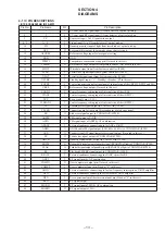
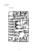
• IC600
µ
PD784216GC-027-8EU (SYSTEM CONTROLLER)
Pin No.
Pin Name
I/O
Pin Description
1
M1
O
Elevator motor (M904) drive signal output
2
M1
O
Elevator motor (M904) drive signal output
3
M2
O
Loading motor (M903) drive signal output
4
M2
O
Loading motor (M903) drive signal output
5
MDMON
O
Mechanism deck system power control output (“H” : Power ON)
6
LES
I
Loading end sensor detection switch (S902) input
7
SES
I
Store end sensor detection switch (S903) input
8
HOME
I
Home position detection switch (S901) input (“L” : Home position)
9
VDD
—
Power supply pin (+5 V)
10
X2
—
Main system clock connecting pin (14 MHz)
11
X1
—
Main system clock connecting pin (14 MHz)
12
VSS
—
GND
13
XT2
—
Sub system clock connecting pin (32.768 kHz)
14
XT1
—
Sub system clock connecting pin (32.768 kHz)
15
RESET
—
System reset input
16
BU IN
I
Backup OFF detection input (“L” : Backup OFF)
17
BUS ON
I
BUS OFF detection of SONY BUS. (“H” : BUS OFF)
18
SQ SY
I
Sub code Q sync input from CXD2652AR (IC200).
19
STR SW
I
STOP switch (S600) input
20
—
O
Not used.
21
CC XINT
I
Interruption status input from CXD2652AR (IC200).
22
—
O
Not used.
23
AVDD
—
Power supply for A/D converter. (+5 V)
24
AVREF0
—
Reference voltage for A/D converter.
25
INIT
I
Initial input pin at reset.
26
TEMP
I
Thermistor connecting pin for temperature detection.
27
EHS
I
Elevator height position detection input
28, 29
—
I
Connect to GND.
30 – 32
—
O
Connect to GND.
33
AVSS
—
Analog GND
34
ERR PWM
O
Error data output (Not used in this set.)
35
—
O
Not used.
36
AVREF1
—
Reference voltage for D/A converter.
37, 38
—
O
Not used.
39
—
—
Not used.
40
MD SI
I
Read data signal input from CXD2652AR (IC200).
41
MD SO
O
Write data signal output to CXA2523AR (IC100) and CXD2652AR (IC200).
42
MD CKO
O
Serial clock signal output to CXA2523AR (IC100) and CXD2652AR (IC200).
43
—
O
Not used.
44
—
—
Not used.
45
UNISI
I
Serial data input for SONY BUS.
46
UNISO
O
Serial data output for SONY BUS.
47
UNI CKI
I
Serial clock input for SONY BUS.
48
LINKOFF
O
Link control signal output for SONY BUS. (“H” : Link OFF)
49
—
O
Not used.
50
—
I
Not used.
51, 52
D-BASS1, 2
O
Digital D-BASS select output 1, 2
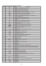
53 – 55
—
O
Not used.
56 – 59
MNT0 – 3
O
Monitor 0 – 3 signal input from CXD2652AR (IC200).
60
AGING
O
Not used.
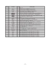
61
AGCHK
O
Not used.
62
TFTON
O
Not used.
Содержание MDX-62
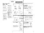
Страница 4: ... 4 5 SECTION 2 GENERAL This section extracted from US Canadian E model s instruction manual ...
Страница 5: ... 6 7 ...
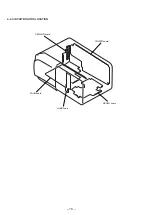
Страница 14: ... 16 4 2 CIRCUIT BOARDS LOCATION SENSOR board POWER board SERVO board LAMP board MAIN board ...
Страница 15: ......
Страница 16: ......
Страница 17: ......
Страница 18: ......
Страница 19: ......
Страница 20: ......
Страница 21: ......

