– 17 –
KV-HA14L80/HA14P50
RM-969
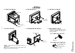
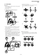
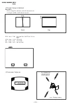
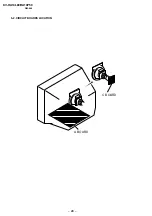
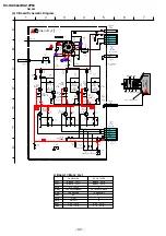
3-3. FOCUS ADJUSTMENT
FOCUS adjustment should be completed before W/B adjustment.
1. Receive digital monoscope pattern.
2. Set "Picture Mode" to "DYNAMIC".
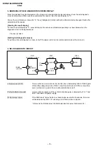
3. Adjust focus VR so that the center of screen becomes
just focus.
4. Change the receiving signal to white pattern and blue back.
5. Confirm magenta ring is not noticeable. Incase magenta is
very obvious, adjust focus VR to take balance of magenta
ring and focus.
3-4. G2 (SCREEN) AND WHITE BALANCE
ADJUSTMENTS
1.
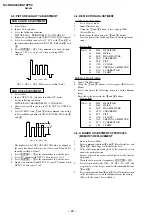
G2 (SCREEN) ADJUSTMENT
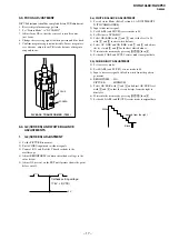
1) Set the PICTURE to normal.
2) Put to VIDEO input mode without signals.
3) Connect R, G and B of the C board cathode to the
oscilloscope.
4) Adjust BRIGHTNESS to obtain the cathode voltage to the
value below.
5) Adjust G2 (screen) on the FBT until picture shows the point
before cut off.
0 V
Cathode setting voltage:
175 V
±
2 (VDC)
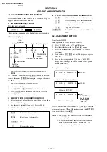
2.a) WHITE BALANCE ADJUSTMENT
1) Set to Service Mode (Refer Section 4-1: ADJUSTMENTS
WITH COMMANDER).
2) Input white raster signal.
3) Set 49 (ABL) and IF (VP2) service mode to 00.
4) Set Picture to DYNAMIC.
5) Select OB (RDR) with
[1]
and
[4]
, and set the level to 25
with
[3]
and
[6]
for best white balance.
6) Select OC 'GDR' and OD 'BDR' with
[1]
and
[4]
, and adjust
the level with
[3]
and
[6]
for the best white balance.
7) Write into the memory by pressing
[MUTING]
then
[0]
.
8) Set back 49 'ABL' and IF 'VP2' service mode to original data.
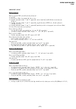
2.b) SUB BRIGHT ADJUSTMENT
1) Set to service mode.
2) Set 49(ABL) and IF (VP2) service mode to 00
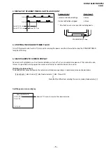
3) Input a staircase signal of black to white from the pattern
generator.
4) BRIGHTNESS .... 50%.
PICTURE ............ MINIMUM
5) Select OE 'SBR' with
[1]
and
[4]
, and adjust OE 'SBR' level
with
[3]
and
[6]
so that the second stripe from the right is
dimly lit.
6) Write into the memory by pressing
[MUTING]
then
[0]
.
7) Set back 49 (ABL) and IF (VP2) service mode to original data.
White
second from the right
Black
FOCUS
SCREEN
FLYBACK TRANSFORMER (T503)

