


81
Menu Contents
Chap
te
r 7
Men
u
s
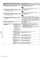
TAPE PROTECTION [Tape protct]: Settings related to tape
and video head protection
Description of settings
FROM STOP [> From STOP]:
Set the time to switch from
stop mode to tape
protection mode.
STOP TIMER [>> STP
timer]:
Set the time to
switch from stop mode to
tape protection mode.
0.5 SEC [>>> 0.5 sec] to 5 MIN [>>> 5 min]:
Select time from
12 settings ranging from 0.5 second to 5 minutes.
Factory default setting:
*
1 MIN [>>> 1 min]
Note
If the value is set to 1 minute or more, the unit enters internal
protection mode in 1 minute, which makes start up slower.
FROM STILL [> From
STILL]:
Set the time to
switch from still search
mode to tape protection
mode. Also select the type
of tape protection mode.
STILL TIMER [>> STL
timer]:
Set the time to
switch from still search
mode to tape protection
mode.
0.5 SEC [>>> 0.5 sec] to 5 MIN [>>> 5 min]:
Select time from
12 settings ranging from 0.5 second to 5 minutes.
Factory default setting:
*
1 MIN [>>> 1 min]
Note
If the value is set to 1 minute or more, the unit enters internal
protection mode in 1 minute, which makes start up slower.
NEXT MODE [>> Next
mode]:
Select the type of
tape protection mode to
follow still search mode
when the time set with
the STILL TIMER menu
item elapses.
*
STEP FWD [>>> Step]:
The tape is advanced at 1/30 times
normal speed for about 2 seconds.
STANDBY OFF [>>> STANDBY]:
Standby off mode
Notes
• The STEP FWD setting is enabled only when “STILL TIMER”
is set to less than 1 minute.
• When HDV format is used, the setting is fixed to STANDBY
OFF.
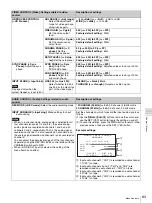
VIDEO CONTROL [Video]: Settings related to video
control
Description of settings
STILL MODE [> STILL mod]:
Select the image to output in
still image mode.
*
AUTO [>> Auto]:
Output field 1 or field 2 as the still image,
according to the position the tape is stopped.
FRAME [>> Frame]:
Output a full frame as the still image.
FIELD1 [>> Field 1]:
Output only field 1 as the still image.
FIELD2 [>> Field 2]:
Output only field 2 as the still image.
Note
When HDV format is used, the setting is fixed to FIELD2.
INT VIDEO SG [> Video SG]:
Select the test signal to be
used when SG is selected as the video input with the
INPUT SELECT buttons.
*
75% COLOR BARS [>> 75% bar]:
75% color bar signal
100% COLOR BARS [>> 100% bar]:
100% color bar signal
BLACK BURST [>> BB]:
Black burst signal
Notes
• When the HD video input is set to SG, the 100% color bar
signal is displayed regardless of whether 75% COLOR
BARS or 100% COLOR BARS is selected.
• With the SD video input set to SG, the 100% color bar signal
is displayed only when the system frequency is set to 50i.
STD/NON-STD [> STD/N-STD]:
Set whether to use the unit in
STD (standard) or NON-STD (non-standard) mode
depending on the condition of composite video or S-video
input.
*
FORCED STD [>> STD]:
The STD mode is always used
(forced STD mode).
FORCED NON-STD [>> NON-STD]:
Use this setting when the
input video signal is unstable (forced NON-STD mode).
OUT REF SEL [> Out Ref]:
When signals are input to both
the VIDEO IN connector and the REF. VIDEO IN
connector, select which signal to use as the reference
signal for playback in EDIT mode.
*
REF VIDEO [>> REF]:
Use the signal input to a REF. VIDEO
IN (SD/HD) connector as the reference video signal. The
input video signal to be edited is required to be in
synchronization with the reference video signal.
INPUT VIDEO [>> INPUT]:
Use the input video signal as the
reference signal.
SETUP REMOVE [> Setup rmv]:
Determine whether or not
to remove black setup (7.5 IRE) from input analog video
signals when converting them into digital signals.
*
OFF [>> OFF]:
Do not remove black setup.
ON (REMOVE) [>> ON]:
Remove black setup.
Note
Displayed only when the system frequency is set to 60i.


