


17
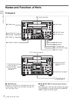
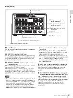
Names and Functions of Parts
Chapt
er 1 Ov
e
rv
ie
w
When an option board is required for signal input, the
corresponding indicator does not light unless the option
board is installed in the unit.
• When HD VIDEO input is selected
1) Downconverted signals (analog video output) are output from the VIDEO
OUT connectors.
• When SD VIDEO input is selected
1) The display follows the recording format setting in the REC FORMAT
menu item
.
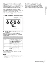
• Audio
The audio inputs for CH1 1/2 and CH2 3/4 can be selected
respectively. The following table shows the relationship
between the audio area indications and the signal selection.
When i.LINK input is selected, the audio input signal is
automatically input from the i.LINK connector, and no
indicator is displayed in the audio area.
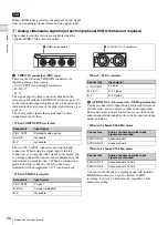
e
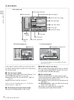
Output signal display
Indicates the output video and audio signal format selected
with the INTERFACE SELECT menu items
Upper line:
Video area (Indicates a format of the analog
video output signals.)
Lower line:
Audio area (Indicates an audio channel output
from the analog audio output connectors.)
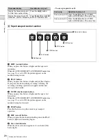
Video area indicators
The indicator corresponding to the selected output analog
video signal format lights.
This selection determines the signals output from the Y/
CPST, Pr/R
–
Y/S
–
C, Pb/B
–
Y/S
-
Y and (SUPER) CPST
connectors on the rear panel as follows.
The superimposed text information output from the
(SUPER) CPST connector can be set to ON (output) or
OFF (do not output) with the CHARA. DISPLAY menu
item
.
• When COMPOSITE/S is selected
Note
Video area
display
Signal format
SG:HD
HD test signal
HD SDI
HD-SDI video signal
1)
i.LINK:HDV
i.LINK compatible HDV format video/
audio signal
Video area
display
Signal format
SG:SD
SD test signal (factory default setting)
COMPOSITE
Composite video signal (optional
HVBK-1505 board required)
S VIDEO
S video (separate Y/C) signal (optional
HVBK-1505 board required)
COMPONENT SD Y, R–Y, B–Y component signal (optional
HVBK-1505 board required)
SD SDI
SD SDI (D1 format) video signal
i.LINK:DV or
i.LINK:DVCAM
i.LINK compatible DVCAM/DV format
video/audio signal
1)
Indicator in
audio area
Signal format
CH-1 1/2
(ANALOG, AES/
EBU, SDI, SG)
The indicator corresponding to the
signal format selected for audio input to
channel 1 (when in 2-channel mode) or
to channels 1 and 2 (when in 4-channel
mode) lights.
ANALOG:
Analog audio signal
(optional HVBK-1505 board
required)
AES/EBU:
Digital audio signal in AES/
EBU format
SDI:
HD-SDI or SD-SDI format digital
audio signal (according to the
video input selection)
SG:
Audio test signal (factory default
setting)
CH-2 3/4
(ANALOG, AES/
EBU, SDI, SG)
The indicator corresponding to the
signal format selected for audio input to
channel 2 (when in 2-channel mode) or
to channels 3 and 4 (when in 4- channel
mode) lights.
ANALOG:
Analog audio signal
(optional HVBK-1505 board
required)
AES/EBU:
Digital audio signal in AES/
EBU format
SDI:
HD-SDI or SD-SDI format digital
audio signal (according to the
video input selection)
SG:
Audio test signal (factory default
setting)
Note
Indicator in
video area
Signal format
COMPOSITE/S
Composite video signal/S-video signal
COMPONENT
SD
Y, R–Y and B–Y component SD video
signals
COMPONENT
HD
Y, Pr and Pb component HD video signals
Connectors
Output signal
Y/CPST
Composite video signal
Pr/R–Y/S-C
C signal
Pb/B–Y/S-Y
Y signal
Indicator in
audio area
Signal format


