background image

59

4-3 TC Menu


C

h

ap
te

r 4


M

enu

 Se
tt

in

g

s

4-3 TC Menu

The TC menu allows you to set time code-related items 
through a single menu. The HOME, TC, VIDEO, AUDIO, 
PF1 and PF2 menus show information that includes the 
VTR operation mode, time code of the current position, 
and the time code type, etc.

To activate the TC menu

Press the TC button.

To change the TC menu page

Press the ALT button.

For details on operation modes, see “4-2 HOME Menu” 
on page 53.

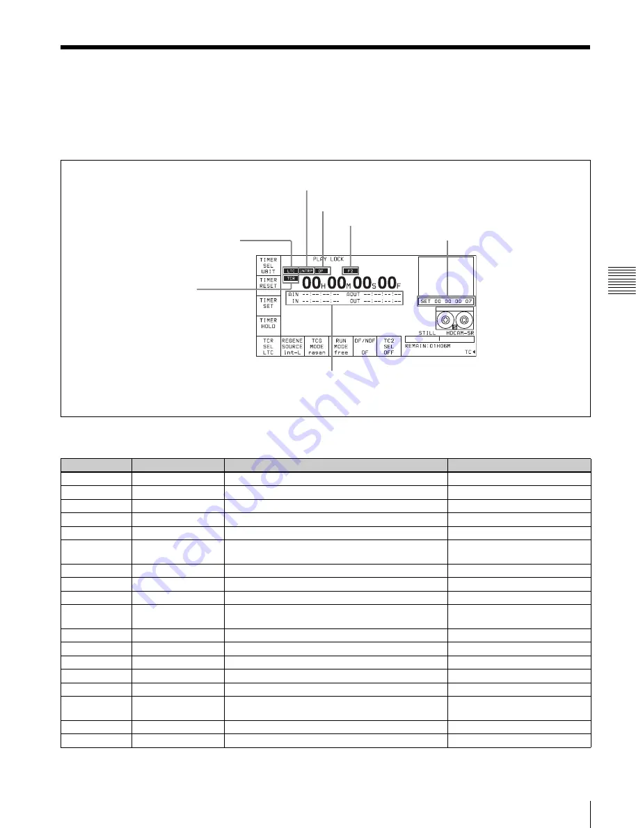
INTRP (interpolation): This appears when time code cannot 
be read correctly and correction has been performed.

VITC: Time code type (LTC/VITC)

F1:  Field number (F1/F2)

Data entry window

TCR: Time data type 
(CTL/TCR/UBR/TCG/UBG/DUR)

AIN: Time data for an AUDIO IN point
AOUT: Time data for an AUDIO OUT point
IN: Time data for an IN point
OUT:  Time data for an OUT point

DF:  Drop frame mode type of playback time code 
(DF/NDF)

Button

Indication

Function

Settings

[F1]

TIMER SEL

Selects time data type.

CTL, TC, UBIT

[F2]

TIMER RESET

Resets the time counter.

[F3]

TIMER SET

Sets the time data.

[F4]

TIMER HOLD

Holds the time counter.

[F5]

TCR SEL

Sets the time code reader.

VITC, auto, LTC 

[F6]

REGENE SOURCE

Selects the internal or external time code generator 
for TCG regeneration.

int-LTC, int-VITC, ext-LTC, SDI-
VITC, SDI-LTC

[F7]

TCG MODE

Sets the time code generator.

regene, prst, auto

[F8]

RUN MODE

Selects the running mode of the time code.

free, rec

[F9]

DF/NDF

Selects drop frame mode.

DF, NDF, auto

[F10]

TC2 SEL

Selects the content of the second line of the time 
code display.

OFF, LTC, auto, VITC, CTL, UBR 
UBV, TCG, UBG

ALT/

[F1]

TAPE TIMER

Selects the CTL display mode.

+ –12H, 24H

ALT/

[F2]

PDPSET MENU

Pulldown time code preset

ALT/

[F3]

TC CONV MENU

Frame conversion time code preset

ALT/

[F4]

PDTC DISP

Pulldown time code display

on, off

ALT/

[F5]

FC CHARA

Superimposition of text data on FC output

on, off

ALT/

[F6]

CHARA SUPER

Specifies superimposition of character information to 
the HD SDI output and HD-SD converter output.

on, off

ALT/

[F7]

CHARA H-POS

Changes the superimposition position (horizontal).

0 to 15

ALT/

[F8]

CHARA V-POS

Changes the superimposition position (vertical).

0 to 15

Содержание HDCAM-SR SRW5800

Страница 1: ...TE RECORDER SRW 5800 FORMAT CONVERTER BOARD HKSR 5001 DIGITAL BETACAM HDCAM PROCESSOR BOARD HKSR 5802 RGB SQ PROCESSOR BOARD HKSR 5803SQ ADVANCED HQ PROCESSOR BOARD HKSR 5803HQ OPERATION MANUAL English 1st Edition Revised 2 ...

Страница 2: ...r moisture does not operate normally or has been dropped To reduce the risk of fire or electric shock do not expose this apparatus to rain or moisture To avoid electrical shock do not open the cabinet Refer servicing to qualified personnel only THIS APPARATUS MUST BE EARTHED When installing the installation space must be secured in consideration of the ventilation and service operation Do not bloc...

Страница 3: ... Canadian ICES 003 For the customers in Europe This product with the CE marking complies with both the EMC Directive and the Low Voltage Directive issued by the Commission of the European Community Compliance with these directives implies conformity to the following European standards EN60065 Product Safety for SRW 5800 EN55103 1 Electromagnetic Interference Emission EN55103 2 Electromagnetic Susc...

Страница 4: ... in Taiwan only For the customers in the USA Lamp in this product contains mercury Disposal of these materials may be regulated due to environmental considerations For disposal or recycling information please contact your local authorities or the Electronic Industries Alliance www eiae org ...

Страница 5: ...ng Up the VTR 3 1 Connecting External Equipment 30 3 1 1 Making HD Digital Connections 30 3 1 2 Making NTSC PAL Digital Connections 31 3 1 3 Cascade Connection 32 3 2 Reference Signals 33 3 2 1 Reference Signals for Output Video 33 3 2 2 Reference Signal Connections 34 3 3 Handling Cassettes 35 3 3 1 Recommended Cassettes 35 3 3 2 Inserting and Ejecting Cassettes 36 3 3 3 Preventing Accidental Era...

Страница 6: ...nd INS AUDIO 54 4 2 4 Still Picture Output FREEZE 54 4 2 5 Setting the Preroll Time PREROLL TIME 55 4 2 6 Selecting DMC Playback DMC 55 4 2 7 Setting the Stop Code STOP CODE 55 4 3 TC Menu 59 4 3 1 Setting the Time Data TIMER SEL RESET SET HOLD 60 4 3 2 Setting the Time Code Reader TCR SEL 63 4 3 3 Setting the Time Code Generator TCG SOURCE MODE 63 4 3 4 Selecting the Time Code Running Mode RUN MO...

Страница 7: ...ANNEL SELECT 95 4 6 5 External Device Digital Audio Edit Preset Command Replace Mode Selection AUDIO EDIT PRESET REPLACE 96 4 6 6 External Device Analog Audio Edit Preset Command Replace Mode Selection ANALOG AUDIO EDIT REPLACE 96 4 7 SET UP Menu 98 4 7 1 VTR SETUP Menu 99 4 7 2 PANEL SETUP Menu 101 Chapter 5 Recording Playback 5 1 Preparing for Recording 103 5 1 1 Setting Switches and Menus 103 5...

Страница 8: ...difying Edit Points 121 6 1 10 Performing Automatic Editing 123 6 2 Advanced Automatic Editing 125 6 2 1 DMC Editing 125 6 2 2 Animation Editing 126 6 3 Manual Editing 127 Appendix Maintenance 128 Head Cleaning 128 Moisture Condensation 128 Specifications 129 Error Messages and Warning Messages 132 Error Messages 132 Warning Messages 133 Error Log Menu 135 Glossary 137 Menu List 139 Items Relating...

Страница 9: ...ol Nos 706 to 158 Items Relating to the Audio Control Nos 807 to 161 Items Relating to Digital Processing Nos 902 to 167 Items Relating to the Pulldown Control Nos A01 to 172 Items Relating to the HKSR 5804 Nos B01 to 174 Other Items Nos T01 to 175 MPEG 4 Visual Patent Portfolio License 181 Index 182 ...

Страница 10: ... 005B 006B SMPTE 291M 292M 299M 372M 424M only when the serial number of this unit is 11001 or higher and ARIB STD B4 allowing the BNC coaxial cable to carry one component video signal twelve digital audio channels and time code in time division multiplex this is separated for conversion to parallel data Audio recording can be switched between the digital audio signal multiplexed with the HD SDI s...

Страница 11: ...e recorded or played back as a dual stream Also the output from two independent cameras can be recorded and played back as a dual stream 3 D signal on a single VTR Applicable system settings 4 2 2 signal 1080 1920 23 98PsF 24PsF 25PsF 29 97PsF 30PsF 50i 59 94i 60i 720 1280 50P 59 94P Note Dual stream recording and playback require the HKSR 5803HQ option Playback compatibility You can select the fo...

Страница 12: ...rporates the Tele File memory label system to allow users to read write and update videocassette management information log data IN OUT points and cue point data on memory labels providing greater efficiency in cassette management and editing 2 Tele File A contact free system for writing reading and modifying video cassette related information on IC memory bearing labels Tele File is a trademark o...

Страница 13: ...e functions allow you to use titles to store and recall menu settings in either the VTR s internal memory banks or Memory Sticks VTR memory banks These memory banks allow you to store up to eight pages of VTR settings in addition to the current VTR settings Factory settings are also stored here allowing the VTR to be reset to these values at any time Memory Sticks Each Memory Stick can hold the cu...

Страница 14: ...ated in 4 4 4 mode up conversion of the output to HD signals are possible as follows depending on the system setting 1080 Up conversion to 1080 720 Up conversion to 720P When the system is operated in 4 4 4 mode no up converted HD output can be obtained HKSR 5803SQ RGB SQ Processor Board This allows you to accept dual link HD SDI input and record and play back in RGB 4 4 4 SQ mode HKSR 5803HQ Adva...

Страница 15: ...nual Volume 3 optional Contains circuit diagrams and block diagrams Installation Manual supplied Provides necessary information to install and operate the VTR For information about changing the video system refer to 1 11 System Setting in the Installation Manual 9 pin Protocol Manual optional Provides information on the 9 pin protocol ...

Страница 16: ...Lower control panel System set up panel 5 Search control section see page 23 3 Tape transport control section see page 21 2 Editing control section see page 20 1 Menu control section see page 18 System set up panel Access by opening the lower control panel see page 24 Upper control panel 4 Display section see page 21 Lower control panel Serial number lower than 11001 Serial number 11001 or higher ...

Страница 17: ...icator remains lit continuously head cleaning or internal inspection is required e EJECT button Pressing this button automatically ejects the cassette after several seconds f Format indicators Digital BETACAM HDCAM HDCAM SR These show the format of the cassette loaded into the unit g REMOTE buttons Press one of the following buttons to select how the VTR is controlled NETWORK 1 This button lights ...

Страница 18: ... In the audio playback level adjustment mode this is used to select the channel to be adjusted b MONITOR R buttons Select the audio signal output from the MONITOR OUTPUT R connector This assigns the desired channel to the MONITOR OUTPUT R connector If you assign more than one channel to the same monitor output connector a mixed audio signal is output You can also make this setting using the VTR SE...

Страница 19: ...on buttons F1 to F10 and shows simultaneously information required for time code display settings and so on 1 E E mode An abbreviation for Electric to Electric mode In this mode video or audio input signals are passed and output only through the VTR s internal circuitry and not through the magnetic conversion system comprising tape and heads f Function buttons Activates the functions in each menu ...

Страница 20: ...SFT shift button Press buttons 0 to 5 while holding down this button to input hexadecimal A to F for user bits Use also in combination with other buttons to perform other operations c RCL recall button Press to recall the previous setting etc d CLR clear button Press to clear input data e SET button Press to finalize input data f INPUT CHECK button While you hold down this button the input signal ...

Страница 21: ...t an edit the results of the edit are played back on the monitor connected to the recorder d REC EDIT recording edit button Press this button while holding down the PLAY button to start recording If you press this button in play mode manual editing begins After setting edit points if you press this button while the AUTO button is lit automatic editing is performed e PLAY button Press to start play...

Страница 22: ...ame delayed with respect to the input video signal LTC OUTPUT Shows the phase of the output LTC LINE Output in phase with the main line HD SDI output FC Output in phase with the FC output Page 6 Meta data HDCAM SR META DATA LINE REC Shows the status of the three lines for metadata recording on this unit META DATA LINE OUT Shows the status of the three lines of main HD SDI output into which metadat...

Страница 23: ... the search dial clicks at the positions for 0 still picture and 10 times normal playback speed HDCAM Digital Betacam or 8 times normal playback speed HDCAM SR b JOG button Press to select jog mode In this mode the button lights up and playback is possible at 1 to 1 times normal speed 2 times normal speed HDCAM HDCAM SR or 3 times normal speed Digital Betacam determined by the setting in the VTR S...

Страница 24: ...mes normal speed Digital Betacam depending on the setting of the VTR SETUP menu item 107 JOG DIAL RESPONSE The dial does not click Variable speed playback mode Noiseless playback is possible in the range from 0 5 to 1 times normal speed HDCAM SR from 1 to 2 times normal speed HDCAM or from 1 to 3 times normal speed Digital Betacam The speed settings can be changed using the menu The dial clicks at...

Страница 25: ...nector Panel Chapter 2 Locations and Functions of Parts 2 2 Connector Panel 1 ANALOG I O section see page 26 2 DIGITAL I O section see page 28 3 Remote input output section see page 29 4 Power supply see page 29 ...

Страница 26: ...nce video signal of the field frequency selected for the format converter output Select HD or SD with the VTR SETUP menu item A08 FC REFERENCE select When HD is selected input an HD tri level SYNC signal for external synchronization When SD is selected input a video signal with chroma burst VBS or a monochrome video signal VS A loop through connection is possible Set the 75Ω termination switch to ...

Страница 27: ...nal time code generator or time code input to the TIME CODE IN connector To select the output signal use the VTR SETUP menu item 613 TC OUTPUT SIGNAL IN REGENE MODE h CUE OUT cue output connector XLR 3 31 male Outputs cue track audio during HDCAM or Digital Betacam playback There is no cue track on an HDCAM SR tape and therefore no output i TIME CODE IN connector XLR 3 32 female Accepts external t...

Страница 28: ...C CHARA buttons are set to ON in the TC menu the output has time data or other text superimposed on the signal This is only valid when the optional HKSR 5001 format converter board is installed d SD SDI OUT 1 2 MONITOR connectors BNC These output three sets of video audio signals When the ALT F6 CHARA SUPER buttons are set to ON in the TC menu time data or other text data is superimposed on the ou...

Страница 29: ...controller d REMOTE 1 I O 9P connector D sub 9 pin female Use this with the supplied 9 pin remote control cable to connect the unit to another SRW 5000 5500 unit or another HD VTR unit to carry out editing with a BVE series editor BVE 700 2000 9000 9100 e NETWORK 1 connector Used for monitoring the VTR by SNMP or for setting or changing VTR settings by HTTP For safety do not connect the connector ...

Страница 30: ... External Equipment 3 1 1 Making HD Digital Connections This example shows the connections when using an SRW 5000 5500 as player and an SRW 5800 as recorder in 59 94i or 60i mode SRW 5000 5500 Player a 9 pin remote control cable SRW 5800 Recorder a The figure shows the SRW 5500 Video monitor HD serial monitor ...

Страница 31: ...Making NTSC PAL Digital Connections This example shows how to connect two VTRs an SRW 5800 as the player and a DVW 2000 D 1 Component Digital VTR as the recorder SRW 5800 Player BNC cable BNC cable Video monitor NTSC PAL monitor DVW 2000 Recorder 9 pin remote control cable ...

Страница 32: ...ltiple SRW series VTRs together for simultaneous recording On the recording VTRs set the VTR SETUP menu item 613 TC OUTPUT SIGNAL IN REGENE MODE to through Note BNC cable Digital video distributor HKPF 103M SRW 5800 Recorder Video monitor HD serial monitor SRW 5800 Recorder a The figure shows the SRW 5500 SRW 5000 5500 Player a ...

Страница 33: ...EFERENCE select extrn SD extrn HD Is there a signal of the correct frequency on the REF INPUT 1 or 2 a connector Is there a signal of the correct frequency on the REF INPUT 1 or 2 a connector Yes Yes Is there an input signal on the HD SDI INPUT connector Yes No No Synchronization with the reference video signal input to the REF INPUT 1 or 2 a connector Synchronization with the video signal input t...

Страница 34: ...cted You can select the following reference signals from menu item 006 EXTERNAL REFERENCE select extrn HD 1080 59 94i tri level SYNC signal extrn SD 525 black burst signal When the 720 50P system is selected You can select the following reference signals from menu item 006 EXTERNAL REFERENCE select extrn HD 1080 50i tri level SYNC signal extrn SD 625 black burst signal When you have directly conne...

Страница 35: ...e following table The recording and playback times for RGB 4 4 4 HQ mode 1080p mode or 4 2 2 dual stream mode are one half those indicated in the table above For playback only Use 1 2 inch HDCAM or Digital Betacam cassettes The maximum playback time is as shown in the following table Playing back a Digital Betacam or HDCAM cassette requires the optional HKSR 5802 Digital Betacam HDCAM Processor Bo...

Страница 36: ...e cassette insertion slot to prevent users from attempting to load another cassette Ejecting the cassette Press the EJECT button The tape is unthreaded and the cassette is automatically ejected This operation takes a few seconds To cancel ejecting a cassette Press any operation button before the cassette is completely ejected The cassette is loaded again and the operation corresponding to the butt...

Страница 37: ... with a data capacity that exceeds a floppy disk Memory Stick is specially designed for exchanging and sharing digital data among Memory Stick compatible products Because it is removable Memory Stick can also be used for external data storage Memory Stick media are available in three sizes standard size compact Memory Stick Duo size and the smallest Memory Stick Micro M2 1 size Once attached to a ...

Страница 38: ...otection technology that uses encryption technology Before using a Memory Stick When you set the Memory Stick erasure prevention switch to LOCK data cannot be recorded edited or erased Data may be damaged if You remove the Memory Stick or turn off the unit while it is reading or writing data You use the Memory Stick in a location subject to the effects of static electricity or electric noise We re...

Страница 39: ...y Memory Stick and MagicGate Memory Stick are trademarks of Sony Corporation Memory Stick Duo and are trademarks of Sony Corporation Memory Stick PRO and are trademarks of Sony Corporation Memory Stick PRO Duo and are trademarks of Sony Corporation Memory Stick ROM and are trademarks of Sony Corporation MagicGate Memory Stick is trademark of Sony Corporation MagicGate and are trademarks of Sony Co...

Страница 40: ...P Menu on page 99 PF ASSIGN menu list This is a list of menu items which can be registered to the HOME TC VIDEO AUDIO PF1 and PF2 menu screens as well as the screen that is displayed by pressing the ALT button the ALT screen This includes all VTR SETUP menu item Press the F4 PF ASSIGN button in the SET UP menu to display this menu For details on registering items see 4 1 3 Registering Items to the...

Страница 41: ...uently used menu items the settings can be carried out together Registering items 1 Press the SET UP button The SET UP menu appears in the display 2 Press the F4 PF ASSIGN button The PF ASSIGN menu appears in the display 3 Press the F1 PAGE button to select the menu where you wish to register an item The selected menu appears and the items currently registered to the menu appear in the middle of t...

Страница 42: ...appears in the display again 4 1 4 VTR Memory Bank Function Eight VTR memory banks are provided for storing up to eight sets of menu settings The contents of all eight VTR memory banks can be stored on a Memory Stick For details on Memory Stick use see 4 1 5 Memory Stick Operations on page 44 For details on adding titles to the contents of the VTR memory bank see 4 1 6 Adding Titles to the Data on...

Страница 43: ...ing you to confirm the operation To cancel the storage operation Press the CLR button 7 Press the F9 COPY button while holding down the SFT button The current menu settings are stored to the VTR memory bank To add or change a title for VTR settings after storing them to the VTR memory bank Move the cursor B to the number of the VTR memory bank where the settings are stored then press the F6 EDIT T...

Страница 44: ... memory card adaptor inserted in the PCMCIA slot When the serial number of this unit is 11001 or higher Lift up the lower control panel push the Memory Stick in and then pull it out For details of opening and closing the control panel refer to the Maintenance Manual When inserting the Memory Stick firmly press the memory card adaptor that accommodates the Memory Stick serial number lower than 1100...

Страница 45: ...ile the confirmation message appears in the display 5 Press the F1 FORMAT CARD button while holding down the SFT button The VTR starts formatting the Memory Stick Storing the contents of the VTR memory banks to a Memory Stick 1 Press the SET UP button The SET UP menu appears in the display 2 Press the F2 MEMORY CARD button The MEMCARD menu appears in the display 3 Press the F8 DIRECTION button to ...

Страница 46: ...ge 49 7 Press the F9 COPY button A message asking you to confirm the operation appears in the display 8 Press the F9 COPY button while holding down the SFT button Storage begins After the storage is complete the title of the VTR memory bank appears on the Memory Stick side Preventing accidental erasure after saving settings Press ALT F2 PROTECT buttons and a symbol will appear to the right of the ...

Страница 47: ...n page 49 Preventing accidental erasure after saving settings Move the cursor B to the cue point set number you wish to save and press ALT F2 PROTECT buttons A symbol will appear to the right of the cue point set number 9 Press the F10 EXIT button The SET UP menu appears again Recalling the contents of a Memory Stick The contents stored in a Memory Stick can be recalled to the current VTR memory b...

Страница 48: ...ay 8 Press the F9 COPY button while holding down the SFT button The VTR recalls the contents of the Memory Stick After the recalling process is complete the title of the memory bank of the Memory Stick appears under the VTR indication 9 Press the F10 EXIT button The SET UP menu appears again Recalling a cue point list from a Memory Stick Recalling a cue point list from a Memory Stick replaces the ...

Страница 49: ...o the item to be titled 2 Press the F6 EDIT TITLE button to display the CURRENT SETUP TITLE EDIT window The VTR enters EDIT mode is entered and the window opens 3 Press the cursor T or t button to select a letter 4 Press the F7 SET LETTER button or the cursor center button The selected letter is entered 5 Repeat steps 3 and 4 to enter more characters To enter a space Press the F5 SPACE button If y...

Страница 50: ... A to VTR B and then to VTR C Even though the optional equipment is different in VTRs A and B the VTR SETUP menu settings are preserved Even though the VTR SETUP menu settings are copied to VTR C after being copied to VTR B the settings from VTR A are copied to VTR C Even though settings are copied for optional equipment that is not present the settings are adjusted and processed by the VTR intern...

Страница 51: ... values in a menu item on page 101 These changed DEFAULT values can be saved in a VTR BANK of the VTR 1 Press the SET UP button The SETUP menu appears 2 Press the ALT button The ALT SETUP menu appears 3 Press the F1 DEFAULT VTR BANK button The DEFAULT VTR BANK screen appears The procedure for saving from CURRENT DEFAULT to DEFAULT BANK saving from DEFAULT BANK or FACTORY PRESET factory setting to ...

Страница 52: ...lling VTR SETUP Data for the SRW 5000 5500 to the VTR Memory Bank VTR SETUP data for the SRW 5000 5500 that have been stored on a Memory Stick can be recalled to the current VTR memory bank 1 Press the SET UP button The SET UP menu appears 2 Press the ALT button The ALT SETUP menu appears 3 Press the F4 IMPORT DATA button The IMPORT DATA menu appears 4 Press the F1 SRW 5000 5500 button The MC5000 ...

Страница 53: ...de Servo lock status Tape format Tape running speed Name of the displayed menu Remaining tape amount Button Indication Function Settings F1 PB EE Selects of output signals PB EE F2 REC INH Disables recording on off F3 ASSEMBLE Selects edit mode and edit channel F4 INS TC Selects TC insert editing mode F5 INS VIDEO Selects VIDEO insert editing mode F6 INS AUDIO Opens the INS AUDIO menu ALT F3 FREEZ...

Страница 54: ... The REC INHIBIT indicator lights crash REC The normal record mode is disabled Use this setting when you want to record only during assemble editing or insert editing video CTL Video and CTL signal recording is inhibited audio CTL Audio and CTL signal recording is inhibited casst This is displayed when recording is inhibited because the record protect plug is set This setting cannot be selected 4 ...

Страница 55: ... entry window disappears 4 2 6 Selecting DMC Playback DMC In DMC Dynamic Motion Control playback mode the VTR plays back a tape segment at a specified variable speed of 1 to 2 times normal playback speed memorizes the speed then plays the segment back at a later time at the memorized speed DMC playback is useful during on the spot telecasts of sporting events for immediate playback and broadcast o...

Страница 56: ...in frame units 1 Press the HOME button The HOME menu screen appears 2 Press the ALT F8 STOP CODE button The STOP CODE menu screen appears 3 Press the F4 DETECT ADJUST button The setting display lights up 4 Change the setting with the cursor R or r button You may also use the MULTI CONTROL knob 5 Press the F4 DETECT ADJUST button The data entry window disappears Note F2 DETECT BEEP button F3 DETECT...

Страница 57: ... correctly recorded regardless of the settings of the F2 DETECT BEEP button and F3 DETECT STOP button a confirmation sound is emitted for 1 second and the unit stops in accordance with the setting of the F4 DETECT ADJUST button If the unit does not stop even after passing the point at which the stop code is recorded repeat the recording operation Checking the recording with the PREVIEW REVIEW butt...

Страница 58: ...e deletion Press the PREVIEW REVIEW button The VTR prerolls 5 seconds before the recording point and starts playback If the unit stops at the point at which the stop code was recorded repeat the deletion operation Checking the deletion with the PREVIEW REVIEW button is only valid in the stop code menu screen Note ...

Страница 59: ... UBIT F2 TIMER RESET Resets the time counter F3 TIMER SET Sets the time data F4 TIMER HOLD Holds the time counter F5 TCR SEL Sets the time code reader VITC auto LTC F6 REGENE SOURCE Selects the internal or external time code generator for TCG regeneration int LTC int VITC ext LTC SDI VITC SDI LTC F7 TCG MODE Sets the time code generator regene prst auto F8 RUN MODE Selects the running mode of the ...

Страница 60: ...the tape running time in hours minutes seconds and frames TC Displays the value read by the time code reader or the value generated by the time code generator To switch between VITC and LTC press the F5 TCR SEL button UBIT Displays user bits data inserted in time code being played back or the user bits data inserted in time code being recorded To switch between VITC and LTC press the F5 TCR SEL bu...

Страница 61: ...ons For example to enter 01H00M30S00F press 1 0 0 3 0 0 0 The leading 0 is not required When the entered value is less than eight digits the leading digit s is are set to 0 when you press the SET button F7 TCG MODE F6 REGENE SOURCE F9 DF NDF Time code and user bits recorded prst DF NDF auto1 TC UB enables TUG UBG values to be recorded Any time code can be specified for the time code generator and ...

Страница 62: ... of the F1 TIMER SEL button Resetting TC or UBIT data The internal time code generator is reset and the time data display becomes 00H00M00S00F TC or 00 00 00 00 UBIT Edit points are not affected Time data read by the time code reader cannot be reset Time data cannot be reset when the internal time code generator is locked to external time codes or to time codes read by the time code reader Setting...

Страница 63: ...ade with the F6 REGENE SOURCE F7 TCG MODE buttons Menu selections and settings are shown in the following table Regenerated signals are selected using the VTR SETUP menu item 608 TCG UBG REGENE MODE setting To check the running of the internal time code generator Press the INPUT CHECK button 4 3 4 Selecting the Time Code Running Mode RUN MODE Press the F8 RUN MODE button to select the time code ru...

Страница 64: ...cting the Content of the Second Time Code Display Area TC2 SEL Select the content of the second time code display area using the F10 TC2 SEL button When the two unit editing display a warning or similar is shown the second time code display area does not appear For details about the warnings see Warning Messages on page 133 4 3 7 Selecting CTL Display Mode TAPE TIMER Press the ALT F1 TAPE TIMER bu...

Страница 65: ... drop frame mode and switches to the non drop frame mode when it is 24 Hz When 24F is selected in the step 3 Skip this step 5 Enter the time code data in the data entry window with numeric buttons 6 Press the SET button to set the input data 7 Press the F2 PDTIME SET button Once the time code is preset it cannot be reverted Operation information display cannot be displayed while the pulldown time ...

Страница 66: ...ENU button The TC CONVERT menu appears 3 Enter the time code in the data entry window with the numeric buttons 4 Press the SET button to set the time code 24 Frames TC 25 Frames TC JUMPING TC 22 00 00 00 20 09 36 00 01 00 01 01 01 00 01 00 Forward direction 01 00 01 00 01 00 00 24 M STARTING TC 01 00 00 00 01 00 00 00 m 00 59 59 23 00 59 59 24 Reverse direction 22 00 00 01 22 07 12 01 Non consecut...

Страница 67: ...LT F4 PD CHARA and ALT F6 CHARA SUPER buttons Contents of superimposed data The example above shows the factory set contents of data By changing the setting of the VTR SETUP menu item 626 DISPLAY INFORMATION select different types of information can also be displayed on the second line a Types of time data Button Setting Connector to which the characters are superimposed ALT F4 on FORMAT CONV OUT ...

Страница 68: ...e code generator UBG User bit data from the time code generator DUR The duration between any two of the four edit points IN OUT AUDIO IN and AUDIO OUT Note Symbol Meaning Display Operation mode A block B block TAPE UNTHREAD Cassette not inserted STANDBY OFF Standby off mode T RELEASE Tension release mode STOP Stop mode PREROLL Preroll mode PLAY Playback mode servo unlocked PLAY LOCK Playback mode ...

Страница 69: ...REMAIN TIME DISPLAY to display remaining time on the tape off Do not display remaining time 10min Display remaining time when it is 10 minutes or less on Always display remaining time Changing the superimpose position The superimpose position can be set to 16 different positions in the horizontal directions 0 to 15 and 24 different positions in the vertical directions 0 to 23 To move in the horizo...

Страница 70: ...cue point data when a cassette is inserted Press the F10 M CUE CLEAR button to select whether to erase cue point data when a cassette is inserted on Erase cue point data off Do not erase cue point data Note Button Indication Function Settings F1 PREV PAGE Shows the previous page F2 NEXT PAGE Shows the next page F4 TELE FILE Opens the TELE FILE menu F5 CUE P ROLL Specifies the preroll time to a cue...

Страница 71: ...To quickly scroll through a list Press the R or r button while holding down the SFT button 4 4 2 Registering Cue Points There are two ways to register cue points 1 by direct registration of the tape address when the ENTRY button is pressed and 2 by the entry of cue point data with the numeric buttons Registering cue points by pressing the ENTRY button 1 Press the ALT F8 PAGE MODE buttons or the AL...

Страница 72: ...ndow then press the F8 PAGE SET button 3 Press the cursor R or r button to move the cursor B to the cue number to be registered To select the cue number directly by the numeric buttons Enter the cue number in the data entry window with the numeric buttons then press the F9 CUENUM SET button 4 Enter the cue point data in the data entry window with the numeric buttons then press the SET button For e...

Страница 73: ... the numeric buttons then press the F9 CUENUM SET button 4 Press the CLR button then press the SET button The cue point display disappears from the data entry window 5 Press the ENTRY button Data for the specified cue number are erased and the data column becomes blank To erase all cue point data Press the CLR button while holding down the SFT button A message asking you to confirm the operation a...

Страница 74: ...DCAM SR format The cassette has a memory label attached as standard and this screen allows operations to read out enter or change the cassette ID identification recording format recording information management information and so on In the HDCAM SR format each recording automatically adds recording information However if the recording time is less than 2 seconds or if when recording ends the measu...

Страница 75: ...olled to the left or right by pressing the T or t button TELE FILE menu display 1 TELE FILE menu display 2 TELE FILE menu display 3 a Tape Format Displays the recording format b OUT Displays the recording end point data c IN Displays the recording start point data d TITLE Displays the cassette title e REC DATE Displays the date the memory label contents were last modified f Date Time Displays the ...

Страница 76: ...RY button 3 Press the cursor T or t button to select a character 4 Press the F7 SET LETTER button or the cursor center button The selected character is entered 5 Repeat steps 3 and 4 to enter more characters To enter a space Press the F5 SPACE button If you enter a wrong character Press the F6 BACK SPACE button to go back Then re enter the character To start the procedure over again Press the F9 C...

Страница 77: ...of the IN point hold down the IN button and in the case of the OUT point hold down the OUT button and press the CLR button to clear the data You can also clear the data by holding down the CLR button and pressing the IN button or OUT button Effect on other data of data entry or update When you enter or update the IN point or OUT point other data is updated as shown in the following table IN point ...

Страница 78: ...PROTECT button After a confirmation message appears hold down the SFT button and press the F7 PROTECT button To insert a new line 1 Use the cursor buttons to position the cursor B below the line where a new line will be inserted To move the cursor with the numeric buttons To move the cursor enter a line number with the numeric buttons then press the F9 CUENUM POINT button The cursor moves to the l...

Страница 79: ...FILE menu screen as follows In the TELE FILE menu screen press the F2 ENTRY POINT button and select IN OUT point Set the VTR SETUP menu item 126 Tele File ENTRY POINT to IN OUT point While the data is being changed if the write protect setting has been made for the whole TELE FILE menu then data changed before the setting was made is rewritten To exit the TELE FILE menu without overwriting the cha...

Страница 80: ...5 Repeat steps 3 and 4 to enter the data To enter a space Press the F5 SPACE button If you make an error in entry Press the F6 BACK SPACE button then repeat the entry To return to the initial screen Pressing the F9 CANCEL button returns to the initial screen To change a character during the operation Press the cursor R button then move the cursor to the title frame with the cursor T or t button ch...

Страница 81: ...ntry cursor is present and the current time data is written To delete a time code 1 Use the cursor buttons to move the cursor to the Time section to be deleted To move the cursor using the numeric buttons Enter the line number using the numeric buttons Then press the F9 CUENUM POINT button The cursor will move to the line specified by the numeric buttons 2 Press the F5 DEL POINT button A deletion ...

Страница 82: ...ion when pressing the IN or OUT button while holding down the ENTRY button the current cue point is entered or it replaces the existing cue point When pressing the ENTRY button only the cue point is entered or replaced regardless of the cursor position To enter or modify IN OUT point data using the numeric buttons 1 Use the cursor buttons to move the cursor to the IN OUT section to be entered or m...

Страница 83: ...n pressing the PREROLL button only the VTR prerolls to the cue point regardless of the cursor position Automatic time data changes during IN OUT point data entry or modification The table below shows the automatic changes that occur in time data when either the IN point or OUT point is changed When IN point data is entered or modified When OUT point data is entered or modified Changing Tk data Use...

Страница 84: ...u enter a wrong character Press the F6 BACK SPACE button to go back Then re enter the character To start the procedure over again Press the F9 CANCEL button to start again To change a character Press the cursor R button to move the cursor to the cut data to be changed Then press the cursor T or t button to move the insertion position 6 Press the F10 SAVE EXIT button The screen that was on before t...

Страница 85: ...to start again To change a character Press the cursor R button to move the cursor to the scene data to be changed Then press the cursor T or t button to move the insertion position 6 Press the F10 SAVE EXIT button The screen that was on before the scene data was entered is displayed again To copy Scn data Move the cursor to the line to which the copied data is to be pasted Then press the RCL butto...

Страница 86: ...ox 6 Press the F10 SAVE EXIT button The screen that was on before the comment data was changed is displayed again Prerolling to a cue point 1 Press the F1 CUE SCAN button repeatedly to specify the direction in which the cursor moves when the PREROLL button is pressed Each press of the button changes the direction as follows FWD forward t REW reverse t unspecified FWD Pressing the PREROLL button ca...

Страница 87: ...ress the cursor buttons to move the cursor to the Time data of the line to be moved Then press the or button Each press of the button moves the line up while each press of the button moves the line down If you perform the procedure above while the cursor is on any other data other than the Time data only the contents selected by the cursor will be moved To move the entire line be sure that the cur...

Страница 88: ...on to go back Then re enter the character To start the procedure over again Press the F9 CANCEL button to start again To change a character Press the cursor R button to move the cursor to the ID or ADMIN box Then press the cursor T or t button to move the insertion position If entered text is longer than the ID or ADMIN box t or T appears to the left or right of the box 6 Press the F10 SAVE EXIT b...

Страница 89: ...t ext input auto F4 MASTER HD Adjusts the Y PB and PR output levels simultaneously prst 0 0 to 141 3 F5 Y HD Adjusts the Y output level prst 0 0 to 141 3 F6 PB HD Adjusts the PB output level prst 0 0 to 141 3 F7 PR HD Adjusts the PR output level prst 0 0 to 141 3 F8 SETUP HD Adjusts the setup level prst 10 0 to 10 0 F9 SYNC HD Adjusts the sync phase prst 128 to 127 F10 FINE HD Fine adjustment of t...

Страница 90: ...s increase or decrease the value by 0 1 You can also change the setting with the MULTI CONTROL knob F8 button SETUP HD Pressing this button makes it active and the cursor R and r buttons increase or decrease the value by 0 5 You can also change the setting with the MULTI CONTROL knob F9 button SYNC HD Pressing this button makes it active and the cursor R and r buttons increase or decrease the valu...

Страница 91: ... item 712 SETUP LEVEL HD Adjusting the sync phase HD Use this setting to precisely match the output phase of the VTR to the reference signal or when using a switcher or other device connected to another VTR to create special effects such as fading wrapping and dissolving To adjust the output signal sync phase with respect to the reference input make this adjustment with the F9 SYNC PHASE button pr...

Страница 92: ...F7 CRM PH ALL buttons prst 0 Numerical value 127 to 127 Adjustable range 30º to 30º This setting can also be carried out in the VTR SETUP menu item 742 CHROMA PHASE ALL Adjusting the black output level HD SD Make this adjustment with the ALT F8 BLK LV ALL buttons prst 0 0 110H Numerical value 31 0 0H to 31 0 220H Adjustable range 31 0 to 31 0 This setting can also be carried out in the VTR SETUP m...

Страница 93: ...D SDI audio output channels does not match the corresponding track number on the tape 4 6 1 Selecting the Audio Input Signal AUDIO IN To select the audio input signal for CH1 to CH12 use the following procedure 1 Press the F1 AUDIO IN button The AUDIO INPUT menu appears together with an audio input selection window Button Indication Function Settings F1 AUDIO IN Accesses the AUDIO INPUT menu SDI A...

Страница 94: ...lection for the digital audio output signal audio multiplexed with HD SDI and SD SDI 1 to 8 channels and AES EBU audio output are targeted on each of channels 1 to 12 use the following procedure Note that when F9 SDOUT EXCHNG in the SDOUT menu is set to ena SD SDI source track selection follows the settings of the SDOUT menu 1 Press the F3 DIGOUT EXCHNG button The DIGOUT menu appears together with...

Страница 95: ...ect the source track for each channel Making input signal selections for individual channels with the numeric buttons 1 Press the cursor T or t button to align the cursor with the channel for which you want to make the selection 2 Press the cursor R or r button to select the source channel to be output To return to the default settings Press the cursor center button The cursor item returns to the ...

Страница 96: ...Audio Edit Preset Command Replace Mode Selection AUDIO EDIT PRESET REPLACE You can replace the channel settings for digital audio edit preset commands received from editors and other external devices For example some devices are capable of issuing digital audio edit preset commands only for channels 1 to 4 CH1 to CH4 This function allows such devices to control channels 1 to 8 on this unit 1 Press...

Страница 97: ... The image of the corresponding channels changes to reflect the settings 3 Press the F10 EXIT button This returns to the AUDIO menu screen You can also make this setting using the VTR SETUP menu item 312 ANALOG AUDIO EDIT PRESET REPLACE See 4 6 5 External Device Digital Audio Edit Preset Command Replace Mode Selection AUDIO EDIT PRESET REPLACE page 96 for information about audio edit preset contro...

Страница 98: ...n You can operate the VTR with a device connected to the REMOTE 1 IN 9P or REMOTE 1 I O 9P connector When the ALT F10 REMOTE 50 PIN buttons are set to on You can operate the VTR with a device connected to the REMOTE 2 PARALLEL I O 50P connector Button Indication Function Settings F1 VTR BANK See 4 1 4 VTR Memory Bank Function on page 42 F2 MEMORY CARD See 4 1 5 Memory Stick Operations on page 44 F...

Страница 99: ...E TC VIDEO AUDIO PF1 and PF2 including the screens displayed by pressing the ALT button you can register about 120 menu items For details on the VTR SETUP menu items see the Appendix Menu List on page 139 For details of the PF assign menu see 4 1 3 Registering Items to the VTR SETUP Menu on page 41 To activate the VTR SETUP menu Press the SET UP button then press the F6 VTR SETUP button Note Butto...

Страница 100: ...ursor R and r button 3 Press the F8 CHANGE DATA button or the cursor t button A window for changing the setting value appears 4 With the F8 CHANGE DATA button or the cursor R and r button or the MULTI CONTROL knob select the setting value When subitems are displayed use the cursor R and r button or the MULTI CONTROL knob to select the subitem to be changed then press the F8 CHANGE DATA button repe...

Страница 101: ... indicating the DEFAULT values move Note If you press the center cursor button first the setting values return to the PRESET values before CURRENT DEFAULT is overwritten and it is not possible to change DEFAULT correctly To return the DEFAULT values to the factory default PRESET values Holding down the CLR and ENTRY buttons at the same time press the center cursor button This saves the factory def...

Страница 102: ...n saver is activated 3 minutes after the last button operation 10min The screen saver is activated 10 minutes after the last button operation 60min The screen saver is activated 60 minutes after the last button operation off The screen saver is not activated Setting the information display screen saver Press the F9 SCREEN SAVER S button on The screen display is periodically switched between normal...

Страница 103: ...arning message is displayed For details see Warning Messages on page 133 Note REMOTE buttons None of these buttons light up MONITOR L R buttons Audio channels to be monitored page 104 Recording level indication Reference level or appropriate recording level page 105 POWER switch ON Indicators Check the reference signal Menu settings F2 REC INH button in the HOME menu off F1 TIMER SEL button in the...

Страница 104: ...o the default settings Press the cursor center button To select the same input signal simultaneously on all twelve channels Press the F9 A IN ALL button This changes the input signal simultaneously on all twelve channels You can also make this setting using the VTR SETUP menu item 830 AUDIO INPUT SELECT Selecting audio signals to be monitored With the MONITOR L or R buttons at the upper left of th...

Страница 105: ...hat it is active 3 Use the MULTI CONTROL knob or the cursor buttons to make the adjustment To escape from the REC LEVEL adjustment mode Press the REC LEVEL mode button at the upper left of the control panel once more The vertical red line at the left of the audio level meter for each channel disappears or turns white To record at the reference level Press the REC LEVEL button to enter REC LEVEL ad...

Страница 106: ...b item REC of the VTR SETUP menu item 017 PB EE SELECT MENU to PB PB Both audio and video playback signals are output 5 1 5 Audio Level Meter Display Modes The audio level meter display changes for each mode depending on the type of cassette in use 5 2 Recording To record follow the procedure below 1 Check that the REC INHIBIT indicator is off then insert a cassette For details on inserting a cass...

Страница 107: ...trol panel once more The vertical blue line at the right of the audio level meter for each channel disappears or turns white To output at the preset level for a level recorded at reference 20 dB outputting at 4 dBm Press the PB LEVEL button to enter PB LEVEL adjustment mode Then make active of the channel that you want to output at the preset level and then then press the MULTI CONTROL knob The se...

Страница 108: ...electing the HD SD Conversion Mode Select the conversion mode using the VTR SETUP menu item 930 DOWNCONVERTER MODE Edge crop mode CROP Horizontal adjustment of the edge cropping Use the VTR SETUP menu item 932 H CROP POSITION DC Letter box mode LETTER BOX When the letter box mode is selected you can select one of the following three conversion methods using the VTR SETUP menu item 931 LETTER BOX M...

Страница 109: ...g the VTR SETUP menu item 107 JOG DIAL RESPONSE Shuttle mode The playback speed corresponds to the angle of rotation of the search dial The playback speed is different depending on the frame frequency of the unit The search dial clicks at the positions for still picture and 8 times normal playback speed for HDCAM or Digital Betacam playback 10 times normal speed Variable mode The playback speed co...

Страница 110: ...DCAM playback the search dial clicks at the positions for still picture and 10 times normal playback speed 3 Set the search dial to center position for still picture or press the STOP button to stop shuttle mode playback To return to normal speed playback Press the PLAY button The audio signal output status is specified by the following settings of the VTR SETUP menu item 017 PB EE SELECT MENU EE ...

Страница 111: ... menu item 101 SELECTION FOR SEARCH DIAL ENABLE to via search key 1 Use either method A or B A Rotate the search dial while holding down the PLAY button to adjust the playback speed The adjustment range is 15 in steps of 1 of the normal playback speed B Press the or button while holding down the PLAY button to adjust the playback speed Every time the or button is pressed the speed changes by 1 fra...

Страница 112: ... button to stop the tape If the MEMORY indicator flashes before the tape reaches the speed variation end point Memory has been exceeded and the VTR cannot store any more data for playback speed variations Notes on the x indicator and the MEMORY indicator The x indicator shows that the tape speed memorization in DMC mode is taking place The MEMORY indicator flashes during playback speed memorizatio...

Страница 113: ...audio Data Non audio data recorded on a tape is detected automatically and played back When non audio data is being played back Below the input display in the audio level meter section the DATA mark lights in white For the audio level meters all regions light The analog audio outputs output to the MONITOR OUTPUT connector and the PHONES jack are turned off The audio output level can be adjusted du...

Страница 114: ...er To use time codes as addresses of edit points the time codes must be recorded on the tape in ascending order As long as they are in ascending order time codes do not have to be continuous The CTL counter automatically interpolates data for editing even if there are breaks in the continuity in the time codes Steps in automatic editing The sequence of steps that are taken to do automatic editing ...

Страница 115: ...nus as shown below F1 TIMER SEL button in the TC menu TC or CTL REMOTE buttons None of these buttons light up Player VTR POWER switch ON Recording level indication recording levels REMOTE buttons 1 9P button lights up F1 TIMER SEL button in the TC menu TC or CTL POWER switch ON Playback level indication playback levels Recorder VTR ...

Страница 116: ... jog or shuttle mode to position the edit point For details on jog or shuttle playback see 5 4 2 Variable Speed Playback on page 109 3 Press the IN or OUT button while holding down the ENTRY button The time data for the IN or OUT point appears in the menu display 4 Repeat steps 1 to 3 to set the remaining edit points Setting edit points with the numeric buttons 1 Press the RECORDER or PLAYER butto...

Страница 117: ...it point OUT point is set the edit point data is activated and the invalid point is automatically deleted Automatic setting of IN points When an IN point is corrected the OUT point is set automatically using the duration of the VTR whose edit points were not changed Split editing Positioning and setting edit points Split editing allows you to set edit points separately for video and audio Set audi...

Страница 118: ...leading digit s is are set to zero s when you press the SET button To delete entered data Press the CLR button 4 Press the SET button to confirm the input data 5 Press any of the IN OUT AUDIO IN and AUDIO OUT buttons When the edit point is set it appears on the editing data display About automatic split edit point setting Split editing requires a total of eight edit points four edit points for vid...

Страница 119: ... be displayed in the time data display window Between IN and OUT points Between IN and AUDIO OUT points Between IN and AUDIO IN points Between OUT and AUDIO OUT points Between OUT and AUDIO IN points Between AUDIO IN and AUDIO OUT points Durations are calculated as follows If both IN and OUT points are set the duration is the time between the points If one of the edit points is not set the duratio...

Страница 120: ... slightly slower than in TC mode This is to maintain the accuracy of the CTL signals You can set up the VTR so that priority is placed on cuing accuracy or speed Change the setting of the VTR SETUP menu item 403 CUEUP BY TC and menu item 404 CUEUP BY CTL Changing the preroll time The preroll time is factory set to 5 seconds but can be set to any time between 0 and 30 seconds in 1 second steps For ...

Страница 121: ... for the recorder and player VTRs the time data for the incorrectly set edit point flash indicating that the VTR cannot perform editing or previewing In this case delete the edit point then set a new one correctly You can also move an edit point position in one frame units Deleting edit points 1 Press the RECORDER or PLAYER button to select the VTR on which to perform the edit point deletion The b...

Страница 122: ...nt appears in the data entry window 2 Press the or button then use the numeric buttons to enter the value to be added or subtracted To cancel the entered value Press the CLR button 3 Press the SET button The result of the addition or subtraction is entered 4 Press one of the IN OUT AUDIO IN or AUDIO OUT button The modified time data for the edit point appears in the time data display Data entry wi...

Страница 123: ...player VTR move as shown in the diagram below a Preroll time Factory set to 5 seconds Can be set from 0 to 30 seconds in units of seconds through the VTR SETUP menu b The post roll time can be set between 0 and 30 seconds in units of seconds using the VTR SETUP menu c Over recording time 2 seconds Preroll point Recorder VTR Player VTR IN point OUT point Post roll point Preroll a Playback mode Play...

Страница 124: ... point and editing stops To confirm the results of the editing Press the PREVIEW REVIEW button to confirm the edit results When the view ends the tape rewinds to the OUT point then stops Modifying edit points for automatic editing later After you perform automatic editing the time data of IN OUT AUDIO IN or AUDIO OUT points remain stored in memory The stored data can be used later to modify edit p...

Страница 125: ...al Betacam or HDCAM format For HDCAM SR format the SRW 5800 cannot be used as the player VTR during DMC editing Tape movement during DMC editing During DMC editing the tape moves as shown in the diagram below Setting edit points and playback speed Use the procedure below to set edit points and playback speeds for DMC editing 1 Press the F3 ASSEMBLE button in the HOME menu or press the respective I...

Страница 126: ...ess the ALT F7 DMC buttons in HOME menu Performing DMC editing After setting the playback speeds in preview mode press the RECORDER button and REC EDIT button DMC editing is performed at the playback speed s stored in memory To confirm the results of DMC editing Press the PREVIEW REVIEW button 6 2 2 Animation Editing Animation editing is a form of insert editing which makes it easier to record a s...

Страница 127: ...t 2 Press the AUTO button to turn it off 3 Press the F3 ASSEMBLE button in the HOME menu or press the respective INSERT button F4 INS TC F5 INS VIDEO or F6 INS AUDIO button to select the edit mode that you want 4 Press the PLAY button Playback starts 5 Press the REC EDIT button at the point where you want to start editing IN point The REC EDIT button lights and editing starts 6 Press the REC EDIT ...

Страница 128: ...ensation If you play a tape under these conditions the tape may adhere to the drum where moisture has collected and become damaged If moisture condenses on the head drum while you are operating the VTR the error message ERROR 10 appears in the time data display section When this error message appears the VTR enters the protection mode and certain operations become inoperable Once the moisture has ...

Страница 129: ...the frame frequency of 25 Hz 124 minutes with the frame frequency of 29 97 Hz Digital Betacam playback time using BCT D124L 124 minutes Fast forward rewind time Approx 4 minutes using BCT 124SRL Search speed Shuttle mode HDCAM SR playback Still to approx 50 times normal playback speed with the frame frequency of 24 Hz Still to approx 48 times normal playback speed with the frame frequency of 25 Hz...

Страница 130: ...ing to SMPTE 424M when the serial number of this unit is 11001 or higher and the optional HKSR 5803SQ or HKSR 5803HQ is installed B OPTION INPUT MONITOR BNC 2 when the optional HKSR 5803SQ or HKSR 5803HQ is installed REF INPUT1 REF INPUT2 OPTION BNC 2 2 loop through HD Trilevel SYNC 0 6 Vp p 75 Ω sync negative SD Black burst NTSC 0 286 Vp p 75 Ω sync negative PAL 0 3 Vp p 75 Ω sync negative Select...

Страница 131: ... SQ Processor Board HKSR 5803HQ Advanced HQ Processor Board HKSR 5804 Network Interface Board RMM 110 Rack Mount Adaptor BCT HD12CL Cleaning Cassette Recommended accessories For details about recommended accessories contact your Sony service representative Memory card adaptor when the serial number of this unit is lower than 11001 MSAC PC4 Memory Stick PC Card Adaptor or equivalent For optionally ...

Страница 132: ...ure to disconnect the power before removing the cassette manually For information about removing cassettes manually refer to the Maintenance Manual Volume 1 Note Item number Display Meaning 01 REEL SLACK THREAD ERROR Tape slack was detected during threading or unthreading 02 REEL SLACK FF REW SEARCH ERROR Tape slack or a broken tape was detected during search fast forward or rewind 03 REEL SLACK P...

Страница 133: ...E The reel table was detected in the L cassette position and S cassette position at the same time 23 THREADING RING POSITION ERROR The threading end and unthreading end were detected at the same time 24 DT HARD ERROR A fault was detected in DT mechanism 26 POWER SUPPLY UNIT TROUBLE A fault was detected in the power supply unit 93 DR INTERFACE ERROR A communications error between the SV CPU board S...

Страница 134: ...dio data channel condition indicator is lit red 10 VITC NOT READ VITC cannot be correctly read from the tape 11 AUDIO PLL UNLOCKED Audio lock generator PLL not locked to the video reference signal 14 NO PB RF SIGNAL Playback heads cannot correctly read digital data from the tape 15 INCONSISTENT EMPHASIS Emphasis information on the tape is inconsistent with the system emphasis status 16 INCONSISTEN...

Страница 135: ...nnot be played with the current system settings 55 VIDEO PLL UNLOCKED Video lock generator PLL not locked to the video reference signal 59 INPUT AUDIO DATA MISMATCH 32 000K The input audio frequency is wrong 5A INPUT AUDIO DATA MISMATCH 47 056K The input audio frequency is wrong 61 TELEFILE MEMORY IS FULL The remaining capacity of the Tele File is low and therefore the next recording will overwrit...

Страница 136: ...meric buttons to change the value To adjust minutes and second to zero Hold down the SFT button and press F8 ZERO button To select daylight saving time and normal time Hold down the SFT button and press F9 SEASON button STANDARD normal time SUMMER daylight saving time one hour ahead of normal time Changing between normal and daylight saving times changes the current time by one hour Even if the ch...

Страница 137: ...l time and the time codes is corrected Specifically two frames are skipped at the beginning of each minute except for every tenth minute so that the frame value for time codes matches that for real time See also Non drop frame mode E E mode Abbreviation for Electric to Electric mode In this mode the signals are passed through the VTR s electronics before output but do not pass through the magnetic...

Страница 138: ...ady for immediate recording or playback The VTR enters standby off mode after remaining in standby on mode for a specified length of time to prevent wear or damage to the tape and video heads Time code A digital signal recorded on the video tape that supplies information such as hour minute second and frame number for each frame to facilitate the setting of edit points or searching for specific sc...

Страница 139: ...nhibiting recording is determined by menu item 003 casst When the recording protection plug on the cassette is pushed in this setting is displayed This setting cannot be selected 003 REC INHIBIT AREA select all crash REC video CTL audio CTL casst Selects the scope to which inhibiting recording applies all All recording is inhibited The REC INHIBIT indicator lights crash REC The normal recording mo...

Страница 140: ...e VTR from a preroll point the IN point is reached after exactly the preroll time has elapsed off Selects normal playback mode on Activates the sync play function for playback Note In sync play mode the time after the tape transport starts until the video and sound appear is longer than in the normal playback mode 008 LOCAL FUNCTION ENABLE all disable all enable local key map When this unit is use...

Страница 141: ...E button is disabled in remote control mode enable The SHUTTLE button operates in remote control mode VAR disable enable disable The VAR button is disabled in remote control mode enable The VAR button operates in remote control mode PREROLL disable enable disable The PREROLL button is disabled in remote control mode enable The PREROLL button operates in remote control mode PREVIEW REVIEW disable e...

Страница 142: ...re output PB PB The playback video and audio signals are output JOG PB PB PB MU Selects the video and audio output signals during jog playback PB PB The playback video and audio signals are output PB MU The playback video signal is output The audio output is turned off VAR PB PB PB MU Selects the video and audio output signals during variable playback PB PB The playback video and audio signals are...

Страница 143: ...how the unit is set to search mode dial direct The unit enters search mode when you rotate the search dial in all modes except recording and edit modes via search key The unit enters search mode when you press the SHUTTLE JOG or VAR button 102 REFERENCE SYSTEM ALARM off on Specifies where or not to display a warning when audio video reference signal selected in item 005 is not present or out of ph...

Страница 144: ... 5 0 5 1 2 3 times normal speed Digital Betacam 113 DT MODE field frame For Digital Betacam HDCAM format Sets the DT operation mode field Enters the field playback mode Field DT mode when the tape speed is 1 to 1 times normal speed Enters the frame playback mode Frame DT mode when the tape speed is 1 to 2 times normal speed frame Enters the frame playback mode Frame DT mode For HDCAM SR format Set...

Страница 145: ...se cue point data off Do not erase cue point data 124 Tele File MENU auto popup off on Specifies whether or not the TELE FILE menu appears automatically when a cassette with a memory label is inserted off The TELE FILE menu does not appear on The TELE FILE menu appears 125 Tele File THREAD COUNTER clear mode not clear when format Specifies whether or not the thread counter is reset when a memory l...

Страница 146: ...t change display color on Changed menu setting values are displayed in yellow DEFAULT SETTING off on off Menu numbers with changed DEFAULT values do not change display color on Menu numbers with changed DEFAULT values are displayed in yellow 132 KNOB MODE set default move window Selects the behavior of the unit when the MULTI CONTROL knob is pressed during VTR SETUP menu operations set default Whe...

Страница 147: ...211 REMOTE 1 PORT IN I O Specifies whether to use one or both of the REMOTE 1 IN 9P and REMOTE 1 I O 9P connectors on the connector panel I I O Use both the REMOTE 1 IN 9P connector and the REMOTE 1 I O 9P connector IN Use only the REMOTE 1 IN 9P connector I O Use only the REMOTE 1 I O 9P connector 212 MONITOR SELECTION FOR VTR TO VTR EDIT MAN AUTO For editing with two SRW 5000 5500 units specifie...

Страница 148: ...within the range of speed specified for the respective formats When an editing control unit such as BVE 9100 is connected for DT editing select wide 305 EDIT FIELD select 1F 2F 1F 2F Selects the start timing for editing when performing tape editing 1F Start editing from field 1 and end on field 2 2F Start editing from field 2 and end on field 1 1F 2F Following received timing commands Note When th...

Страница 149: ...reverse stereo Selects the method for replacing the channel settings for audio edit preset commands received from editors and other external devices normal Assigns edit preset command channels 1 to 8 to track channels 1 to 8 parallel Assigns edit preset command channels 1 to 4 to channel pairs 1 5 to 4 8 reverse Assigns edit preset command channels 1 to 4 to channels 5 to 8 and channels 5 to 8 to ...

Страница 150: ... BLACK VIDEO In the editing interval the monitored signal is a black signal 322 AUDIO PREVIEW MODE SSS SMS During a preview operation this selects the audio signals that can be monitored on the monitor output and line output connectors SSS SOUND SOUND SOUND In the editing interval the monitored signal is the player audio signal or audio input EE signal SMS SOUND MUTING SOUND In the editing interva...

Страница 151: ...end of the tape 408 AUTO CUE UP off on Selects whether or not to cue up when switching from standby off to standby on off No cue up on Cue up to the time code immediately before switching to standby off Item number Item Setting Function 501 STILL TIMER 0 5 sec 5 sec 10 sec 20 sec 30 sec 40 sec 50 sec 1 min 2 min 3 min 4 min 5 min 6 min 7 min 8 min 30 min Select the amount of time after which the V...

Страница 152: ...menu item 502 or 503 set to tension release or when menu item 504 is set to on the drum motor of this unit continues to rotate after tension release mode is entered This menu item sets the time until the unit enters standby off mode and the drum motor stops rotating after entering tension release mode The selectable time ranges from one minute to eight hours Item number Item Setting Function 601 D...

Страница 153: ...ring in the second line UBG Displays UBG TCG Displays TCG UBV Displays UBV UBR Displays UBR CTL Displays CTL VITC Displays VITC auto Displays VITC when the playback speed is in the range 1 2 normal speed and LTC if outside this range LTC Displays LTC off Does not display time data in the second line 605 TAPE TIMER DISPLAY 12H 24H Selects whether the CTL counter operates in 12 hour display mode or ...

Страница 154: ...C data is inserted off VITC data is not inserted 611 VITC POSITION 1 select NTSC 12 281 line 18 281 line 20 283 line When 29 97PsF 59 94i mode is selected on the VTR this setting specifies the lines in which the VITC signal is inserted It can be inserted in any lines from 12 281 to 20 283 Note Items 611 and 612 allow VITC to be inserted in two lines 612 VITC POSITION 2 select NTSC 12 281 line 16 2...

Страница 155: ... regene Regenerates the time code input from the TIME CODE IN connector with the internal time code generator 620 SUPERIMPOSED CHARACTER off on Specifies whether or not to superimpose time data and operating status information on the signal output from the MONITOR connector of SD SDI OUT the SD OUT COMPOSITE connector and MONITOR connector of HD SDI OUTPUT off No information is superimposed on Inf...

Страница 156: ...imer counter display and CTL time data VITC Timer counter display and VITC time data only Timer counter display only 627 CHAR WARNING DISPLAY at dual line mode off on When item 626 is set to anything other than time data only this item specifies whether warning messages flash on the second line or not off Warning messages do not flash on If a warning message exists it flashes Notes Messages that h...

Страница 157: ...hours before STARTING TC 1H The JUMPING TC is set 1 hour before STARTING TC 1H The JUMPING TC is set 1 hour after STARTING TC 2H The JUMPING TC is set 2 hours after STARTING TC 3H The JUMPING TC is set 3 hours after STARTING TC 0H The JUMPING TC is set 1 frame before STARTING TC 633 CHARA ORG TC DISPLAY at dual line mode off on Selects whether to display the time code of the playback tape original...

Страница 158: ...eo signal output from the HD SDI OUTPUT connectors Adjusts the PR level of the video signal 712 SETUP LEVEL HD preset 0 10 0 0 0 10 0 Adjusts the level of the HD video signal output from the HD SDI OUTPUT connectors Adjusts the setup level of the video signal 713 SYNC PHASE HD preset 0 128 0 127 Controls the H sync phase of the HD video signal output from the HD SDI OUTPUT connectors according to ...

Страница 159: ...the video signal 758 R Y LEVEL D1 preset 100 4000H 0 0 0H 141 3 5A70H Adjusts the level of the D1 video signal output from SD SDI OUT Adjusts the R Y level of the video signal 762 SETUP LEVEL CST preset 7 5 IRE 0 0 7 5 10 0 Adjusts the setup level of the analog composite video signal output from SD OUT COMPOSITE MONITOR connector 763 SYNC PHASE SD preset 0 128 0 127 Adjusts the sync phase of the D...

Страница 160: ... be made for each line separately and the Y C signals and odd even fields are blanked simultaneously blank Blank line through Do not blank line all line sub item When this item is selected the other items all take the same values Sub items all line 12 275 line 13 276 line 14 277 line 15 278 line 16 279 line 17 280 line 18 281 line 19 282 line 20 283 line 21 284 line 779 BLANK LINE PAL blank throug...

Страница 161: ...l output from the MONITOR OUTPUT L connector Sub items A MON CH1 disable enable A MON CH2 disable enable A MON CH3 disable enable A MON CH4 disable enable A MON CH5 disable enable A MON CH6 disable enable A MON CH7 disable enable A MON CH8 disable enable A MON CH9 disable enable A MON CH10 disable enable A MON CH11 disable enable A MON CH12 disable enable ...

Страница 162: ...Specifies the type of audio mixing to be conducted on the digital audio signal output to the MONITOR OUTPUT L R connector add Simple addition rms Multiplied average average Simple average 814 LEVEL METER SCALE peak 0 dB reference 0 dB Specifies the mode in which the digital audio level is displayed peak 0 dB Displays minus audio levels with the maximum level set at 0 dB reference 0 dB Displays plu...

Страница 163: ...Selects a non audio input signal The setting is in units of stereo pairs When this is set to other than off the setting of item 830 is invalid AES EBU Selects signal input to DIGITAL I O AES EBU INPUT connector as a data input SDI Selects signal input to HD SDI INPUT A connector as a data input off Treats input as audio Select the input signal with item 830 Sub items CH1 2 CH3 4 CH5 6 CH7 8 CH9 10...

Страница 164: ...ts the audio playback level Sub items A PB LEVEL CH1 A PB LEVEL CH2 A PB LEVEL CH3 A PB LEVEL CH4 A PB LEVEL CH5 A PB LEVEL CH6 A PB LEVEL CH7 A PB LEVEL CH8 A PB LEVEL CH9 A PB LEVEL CH10 A PB LEVEL CH11 A PB LEVEL CH12 A PB LEVEL CUE Item number Item Setting Function ...

Страница 165: ...lows these settings when SDOUT EXCHNG is set to dis disable Sub items DIGITAL OUT CH1 TR1 TR12 DIGITAL OUT CH2 TR1 TR2 TR12 DIGITAL OUT CH3 TR1 TR3 TR12 DIGITAL OUT CH4 TR1 TR4 TR12 DIGITAL OUT CH5 TR1 TR5 TR12 DIGITAL OUT CH6 TR1 TR6 TR12 DIGITAL OUT CH7 TR1 TR7 TR12 DIGITAL OUT CH8 TR1 TR8 TR12 DIGITAL OUT CH9 TR1 TR9 TR12 DIGITAL OUT CH10 TR1 TR10 TR12 DIGITAL OUT CH11 TR1 TR11 TR12 Item number...

Страница 166: ... TR1 TR3 TR12 SD OUT CH4 TR1 TR4 TR12 SD OUT CH5 TR1 TR5 TR12 SD OUT CH6 TR1 TR6 TR12 SD OUT CH7 TR1 TR7 TR12 SD OUT CH8 TR1 TR8 TR12 840 AES EBU INPUT MODE AUTO 48K VLOCK When recording in the HDCAM SR format specifies whether to pass signals input to the DIGITAL I O AES EBU INPUT connector through the sampling rate converter AUTO Input signals pass through the sampling rate converter In this cas...

Страница 167: ...ture is frozen in frame mode only when dynamic tracking is performing a frame operation or is frozen in field mode when dynamic tracking is performing a field operation or when it is not operating 903 FREEZECONTROL FROM KEY PANEL momentary latch Determines the freeze operation control by button operations momentary The picture is frozen only while the button is held down latch The picture is froze...

Страница 168: ... output on Add 16 9 Squeeze identification signal to down converted SD output off Do not add 16 9 Squeeze identification signal to down converted SD output 930 DOWNCONVERTER MODE DC EDGE CROP LETTER BOX SQUEEZE Selects the down converter mode EDGE CROP Selects edge crop mode LETTER BOX Selects letter box mode SQUEEZE Selects squeeze mode 931 LETTER BOX MODE DC 16 9 14 9 13 9 When item 930 is set t...

Страница 169: ...vated by the menu item 941 943 CROSS COLOR CRISP DC preset 4 0 4 15 Sets the crisp level for down converter output cross color 944 V FILTER SELECT mode 0 mode 1 mode 2 mode 3 Sets the vertical interpolation filter coefficient for HD SD converter output 945 D C LEGALIZE DC OFF ON For down converter output selects whether to suppress signals with levels that are lower than the pedestal level OFF Do ...

Страница 170: ...rity mode For up conversion the mode in which the ratio of carrying out conversion from fields is increased 954 DETAIL GAIN UC preset 64 0 64 127 Adjusts the up converter image enhancer Adjusts the sharpness of outlines 955 LIMITTER UC preset 32 0 32 63 Adjusts the up converter image enhancer Adjusts the detail maximum level added to emphasize the original signal 956 CRISP THRESHOLD UC preset 8 0 ...

Страница 171: ...When this item is set to any of the following the same signal is output for LINK A output and LINK B output LINK A The LINK A signal the signal input from the HD SDI INPUT A connector is output LINK B The LINK B signal the signal input from the HD SDI INPUT B connector is output SPLIT A B The monitor display is split vertically in two with the LINK A signal the signal input from the HD SDI INPUT A...

Страница 172: ...d only for dual stream playback recording For double speed playback the LINK A signal the signal input from the HD SDI INPUT A connector is output to fields 1 and 2 983 BORDER off on When the monitor display is split during dual stream playback recording or double speed playback this item specifies whether or not a dividing line is displayed off A dividing line is not displayed on A dividing line ...

Страница 173: ...n converted output signal are synchronized with the reference signal by the REF INPUT 2 connector When the PB E E mode is selected the amount of delay on the A frame of the pulldown output signal for the A frame of the main video signal is fixed to 2 frames 59 94i Notes A warning message appears when the HD reference signal and REF INPUT 2 reference signal are not input or not synchronized lock1 a...

Страница 174: ...ut signal and 30 frame sec time code are synchronized only when this unit is set to PLAY LOCK mode To synchronize the signals set item A05 PD EXT SD REF LOCK MODE to lock2 When editing pulldown output signals with a VTR operating in 30F mode it may not be possible to achieve sync within 5 seconds If this occurs set the preroll time to 7 seconds Also normal operation is not possible with devices en...

Страница 175: ...d from Full to Head after the LUT FtH Is compressed from Full to Head after the LUT Item number Item Setting Function T01 AUTO REPEAT MODE off on Selects the repeating operation of PREVIEW in automatic editing off PREVIEW in automatic editing is not repeated on PREVIEW in automatic editing is repeated To stop press the STOP button T02 INTERNAL VIDEO SIGNAL GENERATOR HD off COLOR BARS 100 COLOR BAR...

Страница 176: ...yback recording 23 98PsF 24PsF 25PsF 29 97PsF 30PsF 50i 59 94i a 60i a 1920 1080 4 2 2 optional HKSR 5803HQ required 50P 59 94P 60P 1920 1080 4 4 4 SQ or HQ For SQ mode optional HKSR 5803SQ or HKSR 5803HQ is required For HQ mode optional HKSR 5803HQ required 23 98PsF 24PsF 25PsF 29 97PsF 30PsF 50i 59 94i 60i 1280 720 4 2 2 With the optional HKSR 5803HQ installed double speed playback and dual stre...

Страница 177: ...e turned off In the case of 4 4 4 signals there is no compatibility between the SQ and HQ modes System frequency HD SDI OUTPUT 1080 720 Recording tape format 23 98PsF 24PsF 25PsF 50i 29 97PsF 59 94i 30PsF 60i 50P 59 94P 60P 50P 59 94P 1080 23 98PsF z a v v v s s s 24PsF a z v v v s s s 25PsF 50i v v z v v s s s 29 97PsF 59 94i v v v z a s s s 30PsF 60i v v v a z s s s 50P x x x x x z v v 59 94P x ...

Страница 178: ... 60i 1080 4 2 2 60P c 25PsF 625 50i a 1080 4 2 2 25PsF 1080 4 2 2 50P c 720 4 2 2 50P 29 97PsF 525 59 94i a 1080 4 2 2 29 97PsF 1080 4 2 2 59 94P c 720 4 2 2 59 94P 30PsF 1080 4 2 2 30PsF 1080 4 2 2 60P c 50i 625 50i a 1080 4 2 2 50i 720 4 2 2 50P 59 94i 525 59 94i a 1080 4 2 2 59 94i 720 4 2 2 59 94P 60i 1080 4 2 2 60i 1080 4 2 2 d 50P 625 50i a 1080 4 2 2 50i 720 4 2 2 50P c 59 94P 525 59 94i a ...

Страница 179: ...4 4 4 25PsF 29 97PsF 525 59 94i 720 4 2 2 59 94P 1080 4 2 2 59 94P c 1080 4 4 4 29 97PsF 30PsF 1080 4 2 2 60P c 1080 4 4 4 30PsF 50i 625 50i 720 4 2 2 50P 1080 4 4 4 50i 59 94i 525 59 94i 720 4 2 2 59 94P 1080 4 4 4 59 94i 60i 1080 4 4 4 60i Digital Betacam e 625 50i 625 50i 720 4 2 2 50P 1080 4 4 4 50i 50P 1080 4 2 2 50i 525 59 94i 525 59 94i 720 4 2 2 59 94P 1080 4 4 4 59 94i 59 94P 1080 4 2 2 5...

Страница 180: ...layback up convert output from the optional HKSR 5001 format converter D1 Y 756 Y LEVEL D1 DC SD b D1 B Y 757 B Y LEVEL D1 DC SD b D1 R Y 758 R Y LEVEL D1 DC SD b D2 VIDEO 740 VIDEO GAIN ALL HD UC SD DC e D2 CHROMA 741 CHROMA GAIN ALL HD UC SD DC e D2 HUE 742 CHROMA PHASE ALL HD UC SD DC e D2 SETUP 762 SETUP LEVEL CST DC SD c 743 BLACK LEVEL ALL HD UC SD DC e f SD Sync Phase 763 SYNC PHASE SD DC S...

Страница 181: ... LICENSE IS GRANTED OR SHALL BE IMPLIED FOR ANY OTHER USE ADDITIONAL INFORMATION INCLUDING THAT RELATING TO PROMOTIONAL INTERNAL AND COMMERCIAL USES AND LICENSING MAY BE OBTAINED FROM MPEG LA LLC SEE HTTP WWW MPEGLA COM MPEG LA is offering licenses for i manufacturing sales of any storage media storing MPEG 4 Visual video information ii distribution broadcasting of MPEG 4 Visual video information ...

Страница 182: ...m Set Up Panel 24 lower control panel Tape transportcontrolsection 21 upper control panel 17 CONTROL PANEL connector 24 CTL timer 62 CUE menu 70 CUE OUT connector 27 Cue point erasing 73 prerolling 73 registering 71 Cursor buttons 20 D Deleting edit points 121 DF drop frame mode 152 DIAG button 19 DIGITAL I O INPUT connectors 28 DIGITAL I O OUTPUT connectors 28 DISPLAY button 19 Display section 21...

Страница 183: ... 105 selecting audio signals 104 setting switches and menus 103 PREROLL button 21 Preroll time setting 55 PREVIEW REVIEW button 21 Pulldown output 173 Pulldown time code displaying 67 presetting 64 R RCL button 20 REC INHIBIT indicator 23 REC LEVEL button 20 REC EDIT button 21 Recording 106 inhibit mode 54 REF SYNC indicators 23 REF INPUT 1 connectors 26 REF INPUT 2 connectors 26 Reference signal ...

Страница 184: ...rocessing 167 items related to editing 147 items related to operation panels 143 items related to prerolling 150 items related to recording protection 151 items related to remote interface 146 items related to the audio control 161 items related to the HKSR 5804 174 items related to the pulldown control 172 items related to the time code 152 items related to the video control 158 items related to ...

Страница 185: ...other than the operation or maintenance of the equipment described in this manual without the express written permission of Sony Corporation Trademarks Intel and Pentium are registered trademarks of Intel Corporation or its subsidiaries in the United States and other countries Microsoft and Windows are registered trademarks of Microsoft Corporation in the United States and or other countries Adobe...

Страница 186: ...Sony Corporation SRW 5800 SY 3 286 523 03 1 2007 ...

Отзывы: