59
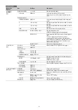
DIAGNOSIS Menu
This menu is for viewing only; camera settings cannot be made using this menu.
However, some items set the conditions for viewing.
DIAGNOSIS
Page name
Page No.
Item
Indication
Description
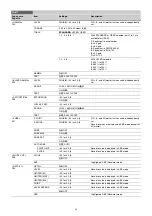
<OPTICAL LEVEL>
D01
CCU
t
CAM
GREEN, YELLOW, RED, NG, NO SIGNAL
Displayed only when a CCU is connected.
CAM
t
CCU
GREEN, YELLOW, RED, NG, NO SIGNAL
CABLE LENGTH
x.x km
Displays the camera cable length.
(Displayed only when a CCU is connected.)
<BOARD STATUS>
D02
OHB
OK, NG
DPR
OK, NG
SY
OK, NG
PS
OK, NG
TX
OK, NG
HOURS METER
xxxx H
Displays the total working time.
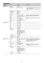
<ROM VERSION>
D03 (U15)
CAMERA APP
Vx.xx
OS
Vx.xx
UPDATER
Vx.xx
PANEL
Vx.xx
Displayed only when HDLA is attached.
SY
Vx.xx
DPR
Vx.xx
PS
Vx.xx
TX
Vx.xx
<SERIAL NO.>
D04
MODEL
HDC5500
NO.
xxxxxxx
EFFECTIVE FUNCTION
Displayed if any option is installed.
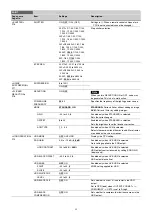
<POWER SUPPLY
STATUS>
D05
Note
This display has a
margin of error for the
display of the electric
supply state of the
camera. Use only as a
guide.
CAM INPUT VOLTAGE
0% to 100%, 100% OVER
Displays the ratio of the input voltage on the
camera to the output voltage on the CCU.
CAM CONSUMPTION
0% to 100%
Displays camera power consumption.
CABLE LENGTH
x.x km
Displays the cable length that a CCU
measured. (Displayed only when a CCU is
connected.)


