background image

19

INDEX COLOR:

 Sets the color of the index.

INDEX WIDTH:

 Sets the width of the index.

MARKER WIDTH:

 Sets the width of the marker.

To set the adjustment sensitivity and display content

You can set the adjustment sensitivity and configure the 
display in the adjusted state using ADJUSTED SIGN on 
the <FOCUS POSITION METER2> page.

SENSE:

 Sets the adjustment sensitivity. Increasing the 

value increases the sensitivity (making 
determination of adjusted state more precise).

NAME DISP:

 Turns the display of the marker name in the 

adjusted state on/off (DISPLAY screen only).

FRAME DISP:

 Turns the display of a color frame 

(adjustment frame) on the screen in the adjusted 
state on/off.

FRAME WIDTH:

 Sets the width of the adjustment frame.

To configure the marker display settings

You can set the marker display using MARKER CONFIG 
on the <FOCUS POSITION METER2> page.

REG:

 Registers a marker at the index position.

DISP:

 Turns the marker display on/off.

COLOR:

 Sets the color of the marker. This also sets the 

color of the adjustment frame.

NAME:

 Sets the name of the marker.

POS:

 Adjusts the marker position manually.

4

Turn the MENU SEL knob/ENTER button to display 
the desired setting and press the MENU SEL knob/
ENTER button.

5

To finish the adjustment, set the DISPLAY switch to 
OFF to exit Menu mode.

Marker registration

You can register a marker for the focus position meter using 
RET/ASSIGNABLE buttons A, B, and C.

Setting the Camera 
Outputs

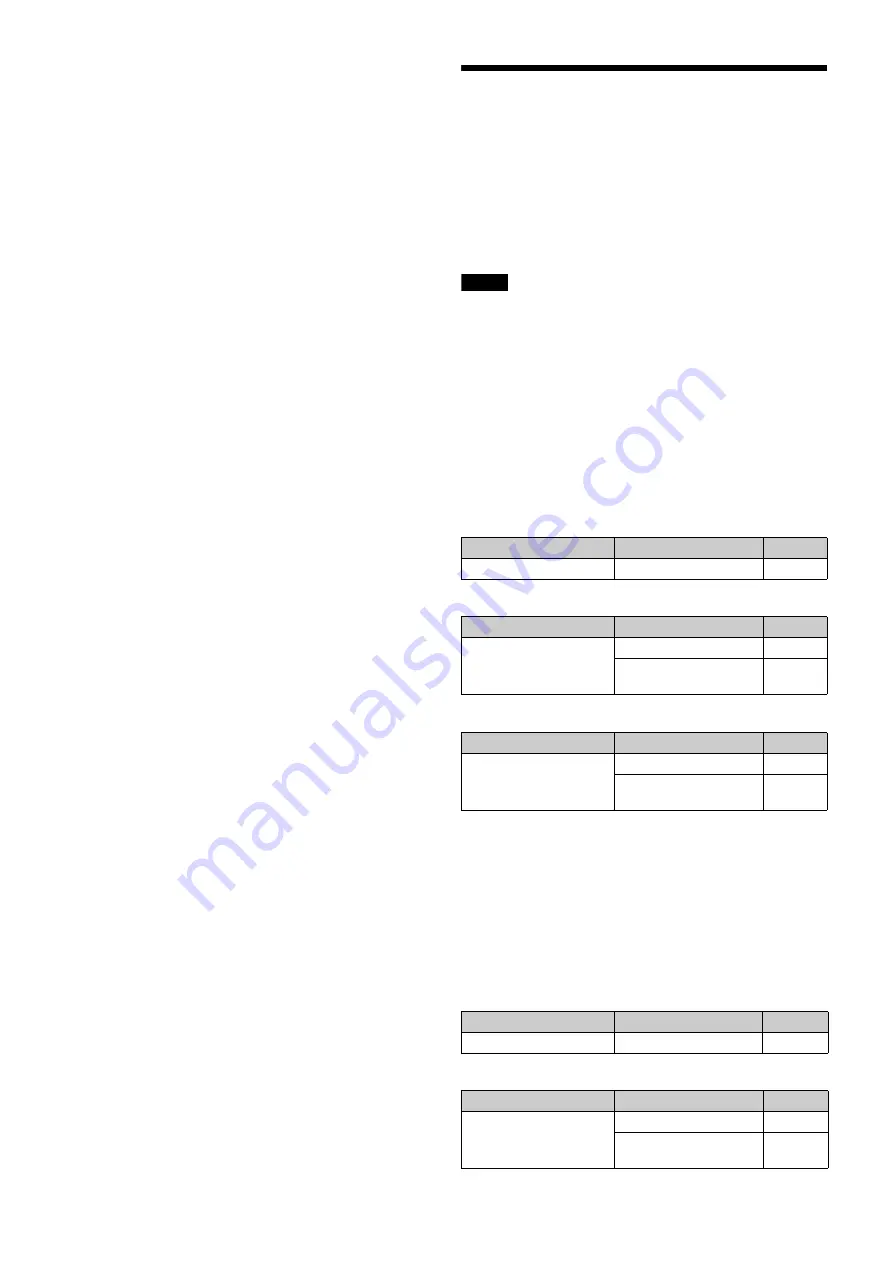
You can specify video signals directly output from the camera, 
with menu operations.
You can display the signal name by attaching a label 
(supplied) for the configured output signal name to the 
connector label area.

Notes

• The MAIN (camera picture), RET (return video), or VF (the 

same picture as that displayed on the viewfinder screen) 
setting is common to SD-SDI and VBS. Different signals 
cannot be output.

• The output is 1080i, even if the format setting is 720P.

Outputting the signal being shot (camera 
picture)

The same textual information as that displayed on the 
viewfinder screen can be added to the output signal by setting 
CHARACTER to “ON” on the <SDI OUT> or <TEST OUT> 
page.

To output as HD-SDI

To output as SD-SDI

To output as VBS

Constantly outputting a return video

• When a camera control unit is connected, one of the signals 

being supplied to the camera control unit can be output from 
the camera.

• The last selected return signal is output.
• The same textual information as that displayed on the 

viewfinder screen can be added to the output signal by 
setting CHARACTER to “ON” on the <SDI OUT> or <TEST 
OUT> page.

To output as HD-SDI

To output as SD-SDI

Menu page

Item

Setting

<SDI OUT>

SDI-MONI OUT

MAIN

Menu page

Item

Setting

<SDI OUT>

SDI-MONI OUT

SD-SDI

DOWN CONVERTER 
SELECT

MAIN

Menu page

Item

Setting

<TEST OUT>

OUTPUT

VBS

DOWN CONVERTER 
SELECT

MAIN

Menu page

Item

Setting

<SDI OUT>

SDI-MONI OUT

RET

Menu page

Item

Setting

<SDI OUT>

SDI-MONI OUT

SD-SDI

DOWN CONVERTER 
SELECT

RET

Содержание HDC3100

Страница 1: ...ating Instructions Before operating the unit please read this manual thoroughly and retain it for future reference 2018 Sony Corporation 4 745 633 11 1 Fiber Color Camera HDC3100 Triax Color Camera HDC3170 ...

Страница 2: ...ck Balance and White Balance 14 Setting the Electronic Shutter 16 Setting the Focus Assist Functions 16 Setting the Focus Position Meter Function 18 Setting the Camera Outputs 19 Viewfinder Screen Status Display 20 Menu Operations 21 Starting Menu Operations 21 Selecting Pages 22 Setting the Menu Items 23 Editing the USER Menu 23 Menu List 27 Menu Tree 27 OPERATION Menu 32 PAINT Menu 40 MAINTENANC...

Страница 3: ... 3 30 or later Note Before starting system operation check that the software version and ROM version of the unit and system devices meet the version requirements Supported Formats The unit supports 1080 59 94i 1080 50i 720 59 94P and 720 50P formats as standard The HDC3170 supports 1080 59 94P and 1080 50P formats as standard You can extend the formats that are supported by installing the followin...

Страница 4: ... type of optical fiber cables used b Set the signal transmission rate for the camera to connect using the following menu item on the camera control unit SYSTEM CONFIG t CAMERA I F t FIBER TRANSMIT RATE For details refer to the operation manual of the camera control unit c To use the HDCU3170 install the HKCU FB30 Optical Fiber Connector Kit USB drive RCP 1500 1000 series Remote Control Panel MSU 1...

Страница 5: ... TRANSMIT For details refer to the operation manual of the camera control unit Lens for ENG EFP VCT 14 Tripod Attachment Tripod HDVF EL75 L750 L770 Viewfinder HDC3170 Triax cable a CAC 6 Return Video Selector Intercom headset CAC 12 Microphone Holder Microphone HDVF EL20 HDVF EL30 Viewfinder HDCU3170 b Camera Control Unit USB drive RCP 1500 1000 series Remote Control Panel MSU 1000 series Master S...

Страница 6: ...ens fixing lever upwards Always keep the lens mount covered with this cap when a lens is not attached i Lens mount To attach a lens j LENS connector 12 pin Connect the lens cable The camera can control the lens functions through this cable k Tripod mount Attach the VCT 14 Tripod Attachment when mounting the camera on a tripod l Camera number Insert the supplied camera number label to display the c...

Страница 7: ... and the output signal and auto knee function is shown in the table below h WHITE BAL white balance memory selection switch To select the white balance adjustment method or the memory used to store the adjusted value when the camera is used in standalone status without connecting a camera control unit PRST preset White balance is adjusted to a preset value corresponding to a color temperature of 3...

Страница 8: ...t to FNT g RET 2 return video 2 button When this button is pressed the picture on the viewfinder screen changes to the return video signal selected using RET ASSIGNABLE button A B or C on the operation panel on the rear of the camera or using the menu You can also assign other functions to this button using the menu displayed on the viewfinder screen Rear a CAMERA POWER switch CCU Power is supplie...

Страница 9: ...urn function is assigned you can change the return signal channel d RET ASSIGNABLE button C DISP MENU switch Press the button to switch the function assigned to the button on the REAR FUNCTION ASSIGN page on off When the return function is assigned press the button to display the return video signal on the viewfinder screen while the button is pressed Turn the button to change the assigned functio...

Страница 10: ...from this connector j TEST OUT connector BNC type To output the analog signal This can also output a VBS signal HD SYNC signal or SD SYNC signal whichever is selected in the menu For details on the output signals see Setting the Camera Outputs page 19 k SDI MONI serial digital interface connector BNC type For HD SDI or SD SDI signal output For details on the output signals see Setting the Camera O...

Страница 11: ...ocal length are in different positions on different lenses Refer to the operation manual for the particular lens Adjusting procedure 1 Set the iris control to manual and open the iris fully 2 Place a flange focal length adjustment chart approximately 3 meters from the camera and adjust the lighting to get an appropriate video output level 3 Loosen the Ff flange focal length ring lock screw 4 With ...

Страница 12: ...ewfinder front rear positioning lever to the unlocked position 2 Slide the viewfinder towards the front or rear of the camera to move it into a good viewing position 3 Set the viewfinder front rear positioning lever to the lock position to secure the viewfinder Detaching the viewfinder Loosen the viewfinder left right positioning ring pull the viewfinder stopper then pull out the viewfinder by sli...

Страница 13: ... the lever down to lock the shoulder pad in the selected position Mounting the Camera to a Tripod Mount the camera to a tripod using a VCT 14 Tripod Attachment Select an appropriate hole from among those at the bottom of the tripod attachment considering the balance of the weight of the camera and the tripod attachment If an inappropriate hole is selected the camera may fall over Check that the si...

Страница 14: ...s connected control is performed from the RCP MSU and the switches on the camera are disabled Black balance adjustment The black balance needs adjustment in situations like the following The first time the camera is used When the camera is used after a long period of disuse When the surrounding temperature changes greatly When the gain value is changed using the setup menus Normally there is no ne...

Страница 15: ...in the same lighting conditions as the subject and zoom in on it so that a white area is obtained in the screen to satisfy the positional and quantitative requirements illustrated below A white object white cloth a white wall etc near the subject may be used in place of a white pattern Note Be careful not to have any spots of high illumination in the rectangle 4 Adjust the lens iris opening With a...

Страница 16: ...t the strength of the red green and blue components varies with the power supply frequency This phenomenon is known as flicker When using the electronic shutter under these lighting conditions there are certain cases in which the flicker is more noticeable In particular color flicker is evident when the power frequency is 60 Hz In areas where the power frequency is 50 Hz setting the shutter speed ...

Страница 17: ...ROMA LEVEL To reduce the chroma components of the video signal only for video signals on the viewfinder 7 Rotate the MENU SEL knob ENTER button to display the desired setting and push on the MENU SEL knob ENTER button 8 To finish the adjustment set the DISPLAY switch to OFF to exit Menu mode Displaying the focus assist indicators The focus assist indicator function extracts the irregularities of a...

Страница 18: ...dicators check that the flange focal length has been precisely adjusted See Adjusting the Flange Focal Length on page 11 for the flange focal length Setting the Focus Position Meter Function The focus position meter function allows you to graphically display the registered focus position marker and the current focus position index graphically on the viewfinder screen You can set the focus to the r...

Страница 19: ...n meter using RET ASSIGNABLE buttons A B and C Setting the Camera Outputs You can specify video signals directly output from the camera with menu operations You can display the signal name by attaching a label supplied for the configured output signal name to the connector label area Notes The MAIN camera picture RET return video or VF the same picture as that displayed on the viewfinder screen se...

Страница 20: ...ter marker or safety zone marker When the DISPLAY switch is set to DISPLAY Items set to ON using the menu or related switches will be displayed on the upper and lower edges of the screen a Zoom position Indicates the approximate position of the zoom lens variator between wide angle 0 and telephoto 99 Shows how close it is to the telephoto side b Lens extender EX is displayed when a lens extender i...

Страница 21: ... transmission only This area shows the light receiving levels in segments CAM Light receiving level at the CCU connector page 8 of the camera CCU Light receiving level at the CAMERA connector of the CCU Menu Operations The menus displayed on the viewfinder screen enable various settings of the camera The following controls are used to operate the menus Starting Menu Operations To display a menu pa...

Страница 22: ...rations such as writing or clearing the reference file DIAGNOSIS menu This menu enables you to confirm the self diagnostic information To select a menu on the TOP MENU screen 1 Rotate the MENU SEL knob ENTER button to align the arrow marker with the desired menu indication 2 Push on the MENU SEL knob ENTER button The CONTENTS page or the last operated page of the selected menu is displayed Selecti...

Страница 23: ... button Repeat steps 1 and 2 By selecting INS on the line below the character list you can enter a space at the cursor position Selecting DEL deletes the character at the cursor position You can return to step 1 without changing the character by selecting RET If you enter the permitted maximum number of characters up to the stop mark at the right end of the line the cursor moves to ESC on the line...

Страница 24: ... added this operation is unnecessary if no item exists on the page as shown in the figure for step 3 then push on the MENU SEL knob ENTER button The EDIT FUNCTION screen appears 5 Move the arrow marker to INSERT and push on the MENU SEL knob ENTER button The page with the last item added appears 6 Add the items 1 Turn the MENU SEL knob ENTER button until the page that has the desired items appears...

Страница 25: ... then push on the MENU SEL knob ENTER button to display the EDIT PAGE screen If a different page is displayed turn the MENU SEL knob ENTER button until the EDIT PAGE screen appears then push on the MENU SEL knob ENTER button to select the page 3 Turn the MENU SEL knob ENTER button to move the arrow marker to where you wish to add the page then push on the MENU SEL knob ENTER button The EDIT FUNCTI...

Страница 26: ... push on the MENU SEL knob ENTER button The EDIT PAGE screen appears again 3 Turn MENU SEL knob ENTER button to move the arrow marker to the position to which you wish to move the page selected in step 1 4 Push on the MENU SEL knob ENTER button The page selected in step 1 is moved to the position selected in step 3 In the above example ZEBRA moves to the 04 position and the VF DISPLAY and followin...

Страница 27: ...CUS ND 5600K IRIS WHITE D EXT GAIN SHUTTER BATT RETURN TALK MESS FOLLOW F AGE ND WHITE 5600K GAIN SHUTTER FAN EXT Y TALLY MARKER LEVEL CENTER SAFETY ZONE EFFECT ASPECT MASK SAFETY VF DETAIL CRISP FREQUENCY FLICKER AREA ZOOM LINK COLOR DE RETURN DISABLE TAIL PEAK COLOR CHROMA LEVEL FOCUS NAME FOCUS FORM 01 U04 02 U05 03 U06 04 U02 FOCUS ASSIST ZEBRA INDICATOR MODE LEVEL GAIN OFFSET AREA MARKER SIZE...

Страница 28: ...ION ANGLE OFFSET SET ZERO ANGLE CLEAR VF OUT CHAR 2 3 4 5 STORE READ USB t CAM WRITE CAM t USB ACTER LEVEL GAIN INSIDE A INSIDE B INSIDE C INSIDE D PinP POSITION SIZE MODE 14 U10 16 REAR FUNCTION ASSIGN 15 A PUSH 17 10 12 U01 13 U09 09 U07 11 EARPHONE RECEIVE SELECT ENG PGM1 PROD PGM2 PGM3 TRACKER SIDE TONE TRACKER EARPHONE OPERATOR FILE READ USB t CAM WRITE CAM t USB PRESET INTERCOM INTERCOM RECE...

Страница 29: ...LEVEL LIMITER M LIMITER WHT LIMITER BLK CRISP LEVEL DEPEND ABS DETAIL 2 P10 SKIN DETAIL P11 USER MATRIX P12 MULTI MATRIX P13 H V RATIO FREQ MIX RATIO KNEE APT DTL H V MODE ABS SKIN DTL SKIN GATE NATURAL SKINDTL ZOOM LINK TELE WIDE CH SW HUE PHASE WIDTH SAT LEVEL R G R B G R G B B R B G MATRIX PRESET LEVEL USER MULTI ADAPTIVE MATRIX PHASE HUE SAT ALL CLEAR GATE MATRIX PRESET USER MULTI Y LIMIT SHUT...

Страница 30: ...DE DROP POINT OFFSET ADJUST SENS OFFSET CANCEL GAIN ROUNDNESS STORE LENS FILE M07 TEST OUT M12 U13 SDI OUT M13 U14 TRUNK M14 GENLOCK M15 DATE M16 BATTERY ALARM M17 OTHERS M18 OPTION KEY M19 OUTPUT VBS OUT CHARACTER GAIN CHROMA V SYNC OUT PHASE H PHASE DOWN CONVERTER SELECT ASPECT SDI 1 SDI MONI OUT CHARACTER EMB AUDIO DOWN CONVERTER SELECT ASPECT TRUNK INTERFACE AUX REMOTE NETWORK TRUNK LINK REFER...

Страница 31: ...USB t CAM WRITE CAM t USB CAM WRITE CAM t USB FILE ID CAM CODE DATE STORE FILE No NAME F NO CENTER MARKER H POS V POS STORE STORE FILE MATRIX FILE F06 1 2 3 4 5 STORE FILE CLEAR ALL READ USB CUSTOM PRESET MATRIX t CAM WRITE CAM t USB FILE ID CAM CODE DATE EFFECTIVE FUNCTION CAM INPUT VOLTAGE CAM CONSUMPTION CABLE LENGTH OPTICAL LEVEL D01 BOARD STATUS D02 ROM VERSION D03 U15 SERIAL NO D04 POWER SUP...

Страница 32: ...ed in the range 0 to 255 no units ABS AUTO Displayed in the units meters or feet set on the lens ABS m Displayed in meters ABS ft Displayed in feet IND 02 U05 ND ON OFF IND Sets whether to be included in the status indications on the viewfinder screen see page 21 NORMAL Specifies the conditions under which the indication is not to be displayed even if IND is ON By specifying the standard or normal...

Страница 33: ...elects whether to set VF DETAIL to OFF for RETURN display FOCUS POSITION METER1 05 FOCUS POSITION METER OFF ON Displays hides the focus position meter NEAR LIMIT 0 to 999 Sets the NEAR limit of the focus position meter FAR LIMIT 0 to 999 Sets the FAR limit of the focus position meter DIRECTION HORIZONTAL VERTICAL Sets the display direction of the focus position meter HORIZONTAL Displayed horizonta...

Страница 34: ...er registering operation is assigned to the dedicated switch COLOR MKR1 2 3 RED GREEN BLUE YELLOW ORANGE PURPLE GRAY BLACK WHITE Sets the color for the triangular area of the marker NAME MKR1 2 3 Up to 8 characters default setting MARKER 1 to 3 Sets the character of Marker Name See To specify a character string on page 23 POS MKR1 2 3 0 to 999 Sets the position of Marker CURRENT FOCUS DIST Display...

Страница 35: ...3 2 3 4 5 STORE Stores a BOX CURSOR FILE name in the camera READ USB t CAM Transfers BOX CURSOR FILE from a USB drive to the camera WRITE CAM t USB Transfers BOX CURSOR FILE from the camera to a USB drive SPIRIT LEVEL 11 INDICATOR ON OFF When this is set to ON BOX MEMORY for CURSOR does not function MODE 1 2 Switches the display method of the indicator REVERSE OFF ON Inverts the movement of the in...

Страница 36: ...2 dB INSIDE A OFF RETURN1 SW RETURN2 SW ENG PROD VF DETAIL 5600K FAN MAX D EXTENDER VF ASSIGN SW1 VF ASSIGN SW2 SPIRIT LEVEL INDICATOR FOCUS ASSIST INDICATOR PinP RET1 SW TOGGLE RET2 SW TOGGLE RET3 SW TOGGLE CURSOR ALL OFF FLAG AWB Note When you turn D EXTENDER ON or OFF noise may be generated This is not a malfunction D EXTENDER does not operate when a 2x speed motion format is selected INSIDE B ...

Страница 37: ...1 REG FOCUS POSITION METER MKR2 REG FOCUS POSITION METER MKR3 REG FOCUS ASSIST INDICATOR Assigns functions executed when you press RET ASSIGNABLE buttons A B and C Default values When A PUSH is selected RETURN1 CAM SW When B PUSH is selected RETURN2 CAM SW When C PUSH is selected RETURN3 CAM SW B PUSH C PUSH A ROT RET CCU CH SEL VF DETAIL LEVEL VF DETAIL CRISP FOCUS ASSIST IND GAIN Assigns functio...

Страница 38: ... PROD EXTENDER D EXTENDER 5600K VF DETAIL SPIRIT LEVEL FOCUS ASSIST PinP VF ASSIGN SW1 VF ASSIGN SW2 VTR S S TALLY R TALLY G TALLY Y INCOM2 Pin2 OFF RETURN1 SW RETURN2 SW RETURN3 SW ENG PROD EXTENDER D EXTENDER 5600K VF DETAIL SPIRIT LEVEL FOCUS ASSIST PinP VF ASSIGN SW1 VF ASSIGN SW2 VTR S S TALLY R TALLY G TALLY Y RETURN 17 RET1 SW SEL CCU RET1 CCU RET2 CCU RET3 CCU RET4 Varies based on the RET1...

Страница 39: ...u 0 dBu 6 dB 0 dB 6 dB OUTPUT LEVEL L CH 0 dBu 6 dBu 12 dBu 18 dBu 20 dBu 24 dBu OUTPUT LEVEL R CH OUTPUT LEVEL 2 EARPHONE 21 EARPHONE RECEIVE SELECT SEPARATE MIX ENG LEFT RIGHT BOTH PROD LEFT RIGHT BOTH PGM1 LEFT RIGHT BOTH PGM2 LEFT RIGHT BOTH PGM3 LEFT RIGHT BOTH TRACKER LEFT RIGHT BOTH SIDE TONE MUTE 1 to 99 50 OPERATOR FILE 22 READ USB t CAM Execute via ENTER Reads the operator file from a US...

Страница 40: ...ecute via ENTER COLOR TEMP 0K to 65535K 3200K BALANCE 99 to 99 0 ATW ON OFF SPEED 1 2 3 4 5 MASTER 3 0 to 12 0 dB 0 0 dB GAMMA P04 LEVEL R G B M 99 to 99 0 R G B and M master values can be independently set COARSE 0 35 to 0 90 0 05 steps 0 45 TABLE STANDARD HYPER USER 1 2 3 4 5 6 7 With STANDARD or USER selected only 1 to 5 are available for USER 1 equivalent to a camcorder 2 gain 4 5 3 gain 3 5 4...

Страница 41: ...d in ABS mode LEVEL DEPEND 99 to 99 0 Absolute value is displayed in ABS mode ON OFF ABS Highlighted ABS Absolute mode DETAIL 2 P10 H V RATIO 99 to 99 0 Absolute value is displayed in ABS mode FREQ 99 to 99 0 Absolute value is displayed in ABS mode MIX RATIO 99 to 99 0 Absolute value is displayed in ABS mode KNEE APT 99 to 99 0 Absolute value is displayed in ABS mode ON OFF DTL H V MODE H V V only...

Страница 42: ...M ITU 709 SMPTE WIDE NTSC EBU ITU 601 CUSTOM1 CUSTOM2 CUSTOM3 CUSTOM4 CUSTOM5 USER ON OFF MULTI ON OFF SHUTTER P14 SHUTTER ON OFF ON OFF Settings in When a remote control unit panel or a CCU is not connected cannot be changed 59 94i 1 100 1 125 1 250 1 500 1 1000 1 2000 50i 1 60 1 125 1 250 1 500 1 1000 1 2000 29 97PsF 1 40 1 60 1 100 1 120 1 125 1 250 1 500 1 1000 1 2000 25PsF 1 33 1 50 1 100 1 1...

Страница 43: ...STORE Execute via ENTER 01 01 to 32 STANDARD Execute via ENTER Reads the standard paint data READ USB t CAM Execute via ENTER Loads 32 scene files from a USB drive to internal memory WRITE CAM t USB Execute via ENTER Writes 32 scene files in the camera s memory to a USB drive FILE ID Max 14 characters Enters a comment for the scene files to be written to a USB drive See To specify a character stri...

Страница 44: ...S LEVEL 99 to 99 0 4 steps APL RATIO 99 to 99 65 IRIS GAIN 99 to 99 0 IRIS CLOSE ON OFF LENS1 M06 F NO DISP CONTROL RETURN Selects the iris indication on the panel when AUTO IRIS is off CONTROL Displays the value from the camera RETURN Displays the value returned from the lens When AUTO IRIS is on the value returned from the lens is always displayed AF DISPLAY ON OFF ALAC AUTO OFF With AUTO select...

Страница 45: ...N M08 MIC1 20 30 40 50 60 dB Can be modified only in standalone operation MIC2 20 30 40 50 60 dB CAMERA NUMBER M09 CAMERA NUMBER 1 to 96 Sets the camera number CCU LINK OFF ON Turns the link with the CCU No on off When on you can set the camera number from the CCU CALL TALLY M10 CCU CALL OFF ON Selects whether TALLY lights for CALL signal CAM CALL OFF ON TALLY GUARD Selects whether to prevent chan...

Страница 46: ...onisation Display only GENLOCK ENABLE DISABLE Displayed only when no CCU connected STATUS FORMAT PHASE V 1024 to 1023 0 H 1700 to 1700 0 DATE M16 DATE TIME 2000 to 2035 01 to 12 00 to 31 00 to 23 00 to 59 DATE FORMAT 1 Y Mn D 2 Mn D 3 D M Y 4 D M 5 M D Y 6 M D Y Year Mn Month numeric M Month character string D Day BATTERY ALARM M17 BEFORE END 11 5 to 17 0 V END 11 0 to 11 5 V OTHERS M18 FAN MODE O...

Страница 47: ... STORE FILE Execute via ENTER Stores the current settings of the reference file items in the reference file in internal memory STANDARD Execute via ENTER Reads the standard values in the reference file in internal memory ALL PRESET Execute via ENTER Resumes the factory preset reference file READ USB t CAM Execute via ENTER Loads a reference file from a USB drive WRITE CAM t USB Execute via ENTER W...

Страница 48: ...s a BOX CURSOR FILE name Sets the cursor to the left of the number when you select BOX CURSOR FILE Sets the cursor to the right of the number when you enter a BOX CURSOR FILE name See To specify a character string on page 23 2 3 4 5 STORE Stores a BOX CURSOR FILE name in the camera READ USB t CAM Transfers BOX CURSOR FILE from a USB drive to the camera WRITE CAM t USB Transfers BOX CURSOR FILE fro...

Страница 49: ...s display has a margin of error for the display of the electric supply state of a camera Use only as a guide CAM INPUT VOLTAGE 0 to 100 100 OVER Displays the ratio of the input voltage for a camera to the output voltage for a CCU CAM CONSUMPTION 0 to 100 Displays camera power consumption CABLE LENGTH x x km Displays the cable length that a CCU measured Displayed only when a CCU is connected Not di...

Страница 50: ...aused by cosmic rays etc This is related to the principle of image sensors and is not a malfunction The white flecks especially tend to be seen in the following cases When operating at a high environmental temperature When you have raised the gain sensitivity Flicker If shooting under lighting produced by fluorescent lights sodium lamps mercury vapor lamps or LEDs the screen may flicker or colors ...

Страница 51: ...lem is detected in the optical block NO USB FLASH DRIVE A USB drive operation was attempted with no USB drive connected USB FLASH DRIVE ERROR An error occurred during access to a USB drive FORMAT ERROR A USB drive operation was attempted with an unformatted USB drive WRITE PROTECTED File writing was attempted with a write protected USB drive FILE ERROR An error occurred while reading a file from a...

Страница 52: ...M32X USM64X USM W3 series USM8W3 USM16W3 USM32W3 USM64W3 USM128W3 USM R series USM4GR USM8GR USM16GR USM32GR USM64GR USM W series USM8W USM16W USM32W USM64W USM M1 series USM8M1 USM16M1 USM32M1 USM64M1 USM SA3 series USM16SA3 USM32SA3 USM64SA3 USM SA2 series USM16SA2 USM32SA2 USM64SA2 USM SA1 series USM8SA1 USM16SA1 USM32SA1 USM64SA1 USM CA1 series USM16CA1 USM32CA1 USM64CA1 USM L series discontin...

Страница 53: ...anced INTERCOM XLR 5 pin female 1 EARPHONE 4 pole mini jack 1 2 polo mono 3 pole stereo 4 pole CTIA standard 4 pole OMTP standard DC IN XLR 4 pin 1 DC 10 5 V to 17 V DC OUT 4 pin 1 DC 10 5 V to 17 V max 0 5 A This may be limited by the imposed load or inputs 2 pin 1 DC 10 5 V to 17 V Max 2 5 A This may be limited by the imposed load or inputs SDI 1 BNC type 1 SDI MONI BNC type 1 TEST OUT BNC type ...

Страница 54: ...SENT OR PROSPECTIVE PROFITS DUE TO FAILURE OF THIS UNIT EITHER DURING THE WARRANTY PERIOD OR AFTER EXPIRATION OF THE WARRANTY OR FOR ANY OTHER REASON WHATSOEVER SONY WILL NOT BE LIABLE FOR CLAIMS OF ANY KIND MADE BY USERS OF THIS UNIT OR MADE BY THIRD PARTIES SONY WILL NOT BE LIABLE FOR THE TERMINATION OR DISCONTINUATION OF ANY SERVICES RELATED TO THIS UNIT THAT MAY RESULT DUE TO CIRCUMSTANCES OF ...

Страница 55: ...55 Dimensions HDC3100 HDC3170 Unit mm inches 138 5 1 2 363 14 3 8 105 4 1 4 186 7 3 8 268 10 5 8 Unit mm inches 152 6 363 14 3 8 105 4 1 4 186 7 3 8 268 10 5 8 ...

Страница 56: ...NCE WITH THE MPEG 4 VISUAL STANDARD MPEG 4 VIDEO AND OR ii DECODING MPEG 4 VIDEO THAT WAS ENCODED BY A CONSUMER ENGAGED IN A PERSONAL AND NON COMMERCIAL ACTIVITY AND OR WAS OBTAINED FROM A VIDEO PROVIDER LICENSED BY MPEG LA TO PROVIDE MPEG 4 VIDEO NO LICENSE IS GRANTED OR SHALL BE IMPLIED FOR ANY OTHER USE ADDITIONAL INFORMATION INCLUDING THAT RELATING TO PROMOTIONAL INTERNAL AND COMMERCIAL USES A...

Отзывы: