


57
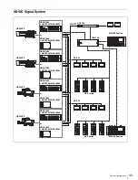
Internal Switches and Internal Boards
b
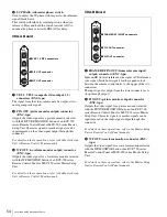
Headset microphone switch 2 (S5)
Set the switch according to the type of microphone of the
headset connected to the intercom connector on the front
panel of this unit:
CARBON:
Carbon microphone (power supply, 20 dB
gain)
ECM:
Electret condenser microphone (power supply, 40
dB gain)
DYNAMIC:
Dynamic microphone (no power supply, 60
dB gain)
c
Internal main power switch
When an abnormality has occurred, and power cannot be
cut off with the POWER switch on the front panel, you
may turn off the unit using the internal main power switch.
When the switch is set to off, pressing the power switch on
the front panel doesn’t turn on the unit.
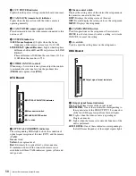
Internal Boards
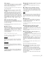
AT Board
a
ACCESS indicator
Shows the status of the “Memory Stick.”
b
“Memory stick” slot
Insert an upgrade “Memory Stick” to upgrade the software
version of this unit.
To insert a “Memory Stick”
Insert the “Memory Stick” into the slot so that the labeled
side of the stick faces you.
When the “Memory Stick” is correctly set, the ACCESS
indicator lights in green. If the indicator stays dark, the
“Memory Stick” may be inserted incorrectly. Check the
stick and reinsert it. To eject the “Memory Stick,” press it
in.
Do not eject a “Memory Stick” when the ACCESS
indicator is lit in red (which means that data is being read
from or written to the “Memory Stick”). This may erase
data stored in the “Memory Stick.”
c
Ethernet indicator
Lights in green when communication via the Ethernet
connector is active.
d
REFERENCE indicators and switch
The switch is used to select the type of sync signal to be
connected to either of the REFERENCE connectors on the
rear panel.
HD:
HD tri-level reference sync signal (local setting)
RMT (remote):
Signal selected on the MSU-900 series
Master Setup Unit
SD:
SD reference sync signal (black burst signal) (local
setting)
When a signal is supplied to the REFERENCE connector,
the REF IN indicator lights. If the type of the input sync
signal does not match the setting on this unit, the
UNLOCK indicator will light.
e
H PHASE switch
Used to adjust the H phase. The switch will return to its
original position when you release it. Press and hold it
towards ADV to advance the phase or towards DELAY for
phase delay.
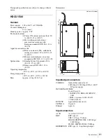
AVP Board
Indication
Meaning
Off
No “Memory Stick” is inserted.
Lit in green
There is a “Memory Stick” in the slot.
Lit in red
Data is being read/written. If you eject the
“Memory Stick” during this operation, the
integrity of the data is not guaranteed. All the
data may be lost.
AT
REF IN
UN
LOCK
H PHASE
REFERENCE
HD
RMT
SD
ADV
DELAY
5
H PHASE switch
1
ACCESS indicator
2
“Memory stick” slot
4
REFERENCE indicators and switch
3
Ethernet indicator
Note
AVP
/1.001
LINE
DELAY
CCU
POWER
CAM
LOCK
CAM POWER
SYSTEM
ON/
OFF
PROD
ENG
2WIRE CANCEL
1
CCU POWER indicator
2
CAM LOCK indicator
5
2WIRE CANCEL controls
4
SYSTEM indicators
3
CAM POWER switch


