


50
Locations and Functions of Parts
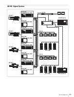
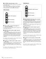
HDCU1500 Rear Panel
a
SDI OUT1, SDI OUT2, SDI OUT3 connectors
(BNC-type)
The signal from the video camera may be output as three
HD-SDI or SD-SDI signals. The SDI OUT1 connector and
the SDI OUT2 connector output the same format signal.
The signal output from the SDI OUT3 connector can be
superimposed character and marker.
b
REFERENCE connectors (BNC-type)
Input an HD tri-level reference sync signal or SD reference
sync signal (black burst signal) to either of the two
connectors.
The input signal is output from the other connector as is
(loop-through output). If loop-through output is not used,
terminate the unused connector at 75 ohms.
The type of reference signal is selected using the setup
menu, or using the MSU-900 series Master Setup Unit.
For details on the setup menu, contact a Sony service or
sales representative.
To use the VBS signal of the HKCU1001 SD Encoder Unit
or the HKCU1003 Multi Interface Unit (when SC phase
lock is required), use an SD reference sync signal (black
burst signal).
c
CHARACTER connector (BNC-type)
Outputs the self-diagnostic results or the setup menu as an
SD monochrome analog video signal.
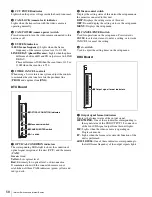
1
SDI OUT1, SDI OUT2, SDI OUT3 connectors
2
REFERENCE connectors
3
CHARACTER/SYNC connector
4
PROMPTER connectors
6
MIC1, MIC2 connectors
7
CAMERA connector
8
Expansion slots
5
Ethernet connector
qf
TRUNK A connector
qg
AC IN connector
qd
WF MODE connector
qs
RCP/CNU connector
qa
MIC REMOTE connector
0
RET1, RET2, RET3 connectors
9
INTERCOM/TALLY/PGM connector
Note


