


32
HCD-LF1
Procedure:
1. Connect an oscilloscope to RF pin and GND pin on the special
jig (J-2501-272-A).
2. Turn the power on.
3. Set the test disc (DVD: TDV-520CSO, CD: LUV-P01) on the
tray and touch the
u
button to playback.
4. Confirm that oscilloscope waveform is clear and check
RFMON signal level is correct or not.
Note:
A clear RFMON signal waveform means that the shape “
◊
” can be
clearly distinguished at the center of the waveform.
SECTION 5
ELECTRICAL ADJSTMENT
DVD SECTION
AUTO SERVO ADJUSTMENT
After parts related to the servo circuit (RF amplifier (IC001), DSP
(IC509), motor driver (IC501), EEPROM (IC903) so on) are
replaced, re-adjusting the servo circuit is necessary. Select “ALL”
at “1. DRIVE AUTO ADJUSTMENT” (Refer to page 26 in TEST
MODE) and adjust DVD-SL (single layer), CD and DVD-DL (dual
layer).
[TEST DISC LIST]
Use the following test disc on test mode.
TDV-520CSO (DVD-SL):
PART No. J-2501-236-A
LUV-P01 (CD):
PART No. 4-999-032-01
TDV-540C (DVD-DL):PART No. J-2501-235-A
Note:
Do not use exiting test disc for DVD.
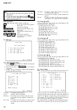
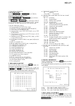
[RFMON Level Check]
By using the special jig (J-2501-272-A), checking RF signal
waveform can carry out easily.
Connection:
CN901
J-2501-272-A
RF
GND
RFMON signal waveform
VOLT/DIV: 200 mV
TIME/DIV: 500 ns
level: 1.09
±
0.2 Vp-p (DVD)
1.05
±
0.2 Vp-p (CD)