background image

HCD-J300

42

42

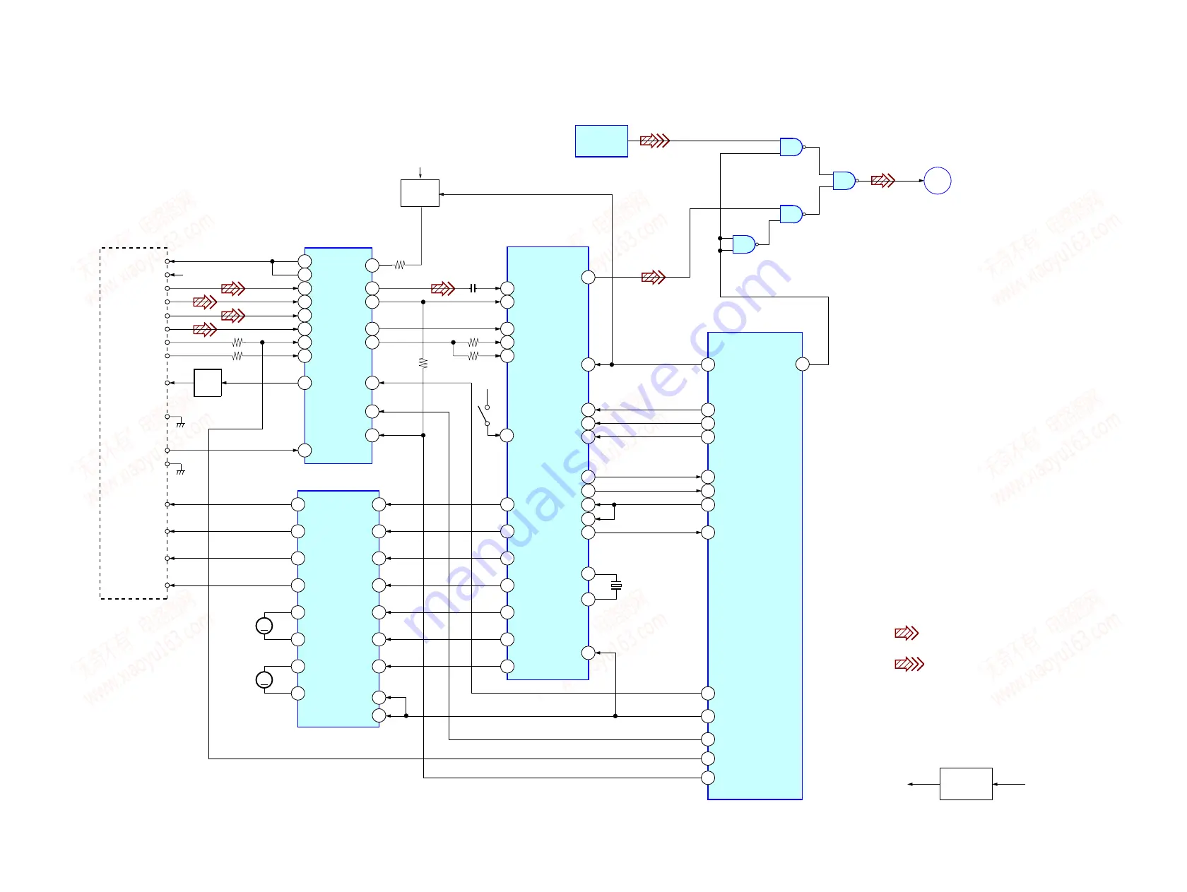
7-2. BLOCK  DIAGRAM  – CD SECTION –

IC503

• Signal Path

: CD (DIGITAL)

:DIGITAL IN (OPTICAL)

OPTICAL PICK-UP

BLOCK

A

B

E

F

LD

VC

VCC

+5V

GND

PD

VR

LD

DRIVE

Q101

RF AMP

DIGITAL

OPTICAL

IN

IC103

VC

27

VFC

25

A

6

B

7

C

8

D

9

E

10

F

11

LD

1

PD

2

C

D

IC702

MOTOR/COIL DRIVE

VO1(+)

14

VO1(-)

13

11

12

15

16

M

SLED

MOTOR

18

17

M

SPINDLE

MOTOR

F+

F-

T+

T-

2

OPIN1(+)

3

OPIN1(-)

5

6

27

26

23

MDP

25

SRDR

30

SFDR

29

TRDR

32

TFDR

31

FRDR

34

FFDR

33

DIGITAL SIGNAL PROCESSOR

IC101

DIGITAL SERVO,

64

D OUT

RFAC

50

28

RFDCO

15

26

RFAC

16

FE

18

TE

12

SW

17

FEI

29

RFDCI

RFDC

43

FE

39

TE

41

SE

40

4

DATA

+3.3V

DATA

6

CLOK

CLK

5

XLAT

XLT

76

SQSO

SQSO

7

SENS

SENS

26 SSTP

2

XRST

9

STBY1

20

STBY2

69

XTSL

MASTER CONTROL

IC306(1/3)

21

OPT-SEL

CD-DATA

34

8

SCLK

77

SQCK

SCLK

15

SCOR

SCOR

71

XTAI

72

XTAO

CD-CLK

27

XLT

22

SQ-DATA-IN

32

SENS

23

SQ-CLK

33

SCOR

19

XTSL

CTRL1(1-2)

3

LDON

LDON

25

CD_XRST

XRST

39

BU_PWM 1

PWM1

28

BU_PWM 2

PWM2

26

BU_PWM 3

PWM3

24

VO2(-)

VO2(+)

VO4(+)

VO4(-)

VO3(-)

VO3(+)

OPIN2(+)

OPIN(2-)

OPIN4(+)

OPIN4(-)

OPIN3(-)

A

MD

SECTION

(Page 44)

RFC

SWITCH

Q102

IC551

+3.3V

REG

Q103,D101

SELECTOR

1

2

3

4

5

6

9

8

10

11

12

13

X101

33.8MHz

S101

LIMIT

IN

SWITCH

+5V

+5V

+3.3V

DIN

w w w . x i a o y u 1 6 3 . c o m

Q Q 3 7 6 3 1 5 1 5 0

9

9

2

8

9

4

2

9

8

T E L

1 3 9 4 2 2 9 6 5 1 3

9

9

2

8

9

4

2

9

8

0

5

1

5

1

3

6

7

3

Q

Q

TEL  13942296513  QQ  376315150  892498299 

TEL  13942296513  QQ  376315150  892498299 

http://www.xiaoyu163.com

http://www.xiaoyu163.com

Содержание HCD-J300

Страница 1: ...rated 30 30 W 6 ohms at 1 kHz DIN Continuous RMS power output reference 35 35 W 6 ohms at 1 kHz 10 THD Music power output reference 85 85 W Other models The following measured at 230 V AC 60 Hz DIN power output rated 30 30 W 6 ohms at 1 kHz DIN Continuous RMS power output reference 35 35 W 6 ohms at 1 kHz 10 THD The following measured at 220 V AC 60 Hz DIN power output rated 24 24 W 6 ohms at 1 kH...

Страница 2: ...AM tuner section Tuning range European model 531 1 602 kHz with the tuning interval set at 9 kHz Other models 530 1 710 kHz with the tuning interval set at 10 kHz 531 1 602 kHz with the tuning interval set at 9 kHz Antenna AM loop antenna external antenna terminal Intermediate frequency 450 kHz General Power requirements European model 230 V AC 50 60 Hz Hong Kong model 220 240 V AC 50 60 Hz Other ...

Страница 3: ... is a copy of commercially available music software p The Serial Copy Management System prevents making a digital copy see page 47 1 SERVICING NOTES 4 2 GENERAL 9 3 DISASSEMBLY 11 4 TEST MODE 21 5 MECHANICAL ADJUSTMENTS 27 6 ELECTRICAL ADJUSTMENTS 27 7 DIAGRAMS 7 1 CIRCUIT BOARDS LOCATION 40 7 2 BLOCK DIAGRAM CD SECTION 42 BLOCK DIAGRAM MAIN SECTION 43 BLOCK DIAGRAM MD SECTION 44 BLOCK DIAGRAM PAN...

Страница 4: ...uman body During repair pay attention to electrostatic break down and also use the procedure in the printed matter which is included in the repair parts The flexible board is easily damaged and should be handled with care FOR CD NOTES ON LASER DIODE EMISSION CHECK The laser beam on this model is concentrated so as to be focused on the disc reflective surface by the objective lens in the optical pi...

Страница 5: ... mechanism deck 4 Rotate it in the direction of the arrow A A B 5 Move it in the direction of the arrow B 6 Clean the lens block by cotton swab Optical pick up www xiaoyu163 com QQ376315150 9 9 2 8 9 4 2 9 8 TEL 13942296513 9 9 2 8 9 4 2 9 8 0 5 1 5 1 3 6 7 3 Q Q TEL 13942296513 QQ 376315150 892498299 TEL 13942296513 QQ 376315150 892498299 http www xiaoyu163 com http www xiaoyu163 com ...

Страница 6: ...rd CN304 CN301 CN801 CN1001 CD mechanism deck CDM55F K4BD43 Loading board Main board CD board CN1 CN308 CN101 CN302 www xiaoyu163 com QQ376315150 9 9 2 8 9 4 2 9 8 TEL 13942296513 9 9 2 8 9 4 2 9 8 0 5 1 5 1 3 6 7 3 Q Q TEL 13942296513 QQ 376315150 892498299 TEL 13942296513 QQ 376315150 892498299 http www xiaoyu163 com http www xiaoyu163 com ...

Страница 7: ...mechanism deck Main board CN301 CN303 www xiaoyu163 com QQ376315150 9 9 2 8 9 4 2 9 8 TEL 13942296513 9 9 2 8 9 4 2 9 8 0 5 1 5 1 3 6 7 3 Q Q TEL 13942296513 QQ 376315150 892498299 TEL 13942296513 QQ 376315150 892498299 http www xiaoyu163 com http www xiaoyu163 com ...

Страница 8: ...uring IOP Check the deterioration of the optical pick up laser TE TRK error signal Traverse adjustment VC Reference level for checking the signal RF RF signal Check jitter FE Focus error signal I 3V CN105 IOP TE VC GND FE RF I 3V Iop GND TE FE VC RF I 3V IOP GND TE FE VC RF 1 7 for MDM 7B www xiaoyu163 com QQ376315150 9 9 2 8 9 4 2 9 8 TEL 13942296513 9 9 2 8 9 4 2 9 8 0 5 1 5 1 3 6 7 3 Q Q TEL 13...

Страница 9: ...O MONO 4 37 SYNCHRO REC 6 19 20 40 TAPE m M qs 39 TAPE X qj 39 41 TAPE x wg 20 39 41 52 TAPE Y wh 39 41 TUNING MODE 3 36 37 TUNING 2 36 37 VOLUME qg 1 wj wh wg wf wd ws 2 3 7 8 9 0 qa qs qd qf qg qh qj qk ql w wa 45 6 BUTTON DESCRIPTIONS 1 power 1 7 18 26 37 43 45 52 z MD qa 21 24 25 52 Z PUSH 5 39 z TAPE 0 41 This section is extracted from instruction manual www xiaoyu163 com QQ376315150 9 9 2 8 ...

Страница 10: ...qa 10 12 15 17 25 x qs 11 12 15 17 19 20 25 X w 11 15 Setting the time 1 Turn on the system 2 Press CLOCK TIMER SET on the remote If you are setting the clock for the first time go to step 5 3 Press or on the remote repeatedly until CLOCK SET appears in the display 4 Press ENTER YES on the remote The hour indication flashes 5 Press or on the remote repeatedly to set the hour 6 Press ENTER YES or C...

Страница 11: ...ECHANISM DECK Page 12 CONTROL BOARD LED BOARD HEAD PHONE BOARD Page 17 LOADING MOTOR ASSEMBLY SPINDLE MOTOR ASSEMBLY SLED MOTOR ASSEMBLY Page 17 MD SECTION Page 14 BD BOARD Page 15 OPTICAL BOARD Page 13 BASE UNIT BU K4BD43 Page 19 CAM CDM55 Page 18 OVER WRITE HEAD HR901 Page 16 CD MECHANISM DECK CDM55F K4BD43 Page 18 MD MECHANISM DECK MDM 7B DIGITAL BOARD Page 14 www xiaoyu163 com QQ376315150 9 9 ...

Страница 12: ...s KTP 3 6 1 Four screws BTP 3 8 3 Three screws BVTT 2 6 5 7 Two screws BVTT 2 6 5 9 Two screws BVTT 2 6 5 8 MD bracket R q MD bracket L 5 Connector 6 core from tape mechanism deck qa Tape mechanism deck 6 TC board 4 Claw 3 TC block section 2 Top panel 1 Flat type wire 18 core CN301 2 Flat type wire 9 core to TC board from tape mechanism deck Note Follow the disassembly procedure in the numerical o...

Страница 13: ...ector CN306 4 Lead with connector 5 Lead with connector q Lead with connector 6 Two screws BTP 3 8 9 Two screws BTP 3 8 7 Screw KTP 3 6 8 Screw KTP 3 6 qa Six dowels qs Front panel section www xiaoyu163 com QQ376315150 9 9 2 8 9 4 2 9 8 TEL 13942296513 9 9 2 8 9 4 2 9 8 0 5 1 5 1 3 6 7 3 Q Q TEL 13942296513 QQ 376315150 892498299 TEL 13942296513 QQ 376315150 892498299 http www xiaoyu163 com http w...

Страница 14: ...ore CN102 6 Two screws BVTP 3 8 1 Two screws BVTP 3 8 8 Digital board 7 MD bracket 3 Shield MD q Two insulators 9 Two insulators qa MD mechanism deck MDM 7B 2 Lead with connector www xiaoyu163 com QQ376315150 9 9 2 8 9 4 2 9 8 TEL 13942296513 9 9 2 8 9 4 2 9 8 0 5 1 5 1 3 6 7 3 Q Q TEL 13942296513 QQ 376315150 892498299 TEL 13942296513 QQ 376315150 892498299 http www xiaoyu163 com http www xiaoyu1...

Страница 15: ...solderings LOADING 4 Remove the three solderings M102 M101 M103 S102 6 Flexible board CN101 7 Connector CN104 8 BD board 5 Screw B P TRI 2 6 CZN www xiaoyu163 com QQ376315150 9 9 2 8 9 4 2 9 8 TEL 13942296513 9 9 2 8 9 4 2 9 8 0 5 1 5 1 3 6 7 3 Q Q TEL 13942296513 QQ 376315150 892498299 TEL 13942296513 QQ 376315150 892498299 http www xiaoyu163 com http www xiaoyu163 com ...

Страница 16: ...I 2 6 CZN 5 Two screws KTP 2 6 6 Main shaft 7 Flexible board 8 OP sub secion 2 Base BU D 4 Base BU A www xiaoyu163 com QQ376315150 9 9 2 8 9 4 2 9 8 TEL 13942296513 9 9 2 8 9 4 2 9 8 0 5 1 5 1 3 6 7 3 Q Q TEL 13942296513 QQ 376315150 892498299 TEL 13942296513 QQ 376315150 892498299 http www xiaoyu163 com http www xiaoyu163 com ...

Страница 17: ... 5 LCD holder R 3 LED board 6 Knob VOL assembly 7 Hexagon nut 4 Three tapping screws DIA 2 6 8 IT3B 9 Ten tapping screws DIA 2 6 8 IT3B qd four tapping screws DIA 2 6 8 IT3B 8 Ten tapping screws DIA 2 6 8 IT3B qa Flat type wire 25 core CN801 qs Control board qfHead phone board qhConnector CN306 qgLead with connector q Lead with connector www xiaoyu163 com QQ376315150 9 9 2 8 9 4 2 9 8 TEL 13942296...

Страница 18: ...A While pushing this claw in the direction of the arrow B release the lock Release the lock 3 Pull out the tray 4 Belt CDM55 5 Spacer 55 6 Pulley LDG 7 Roller q Cam CDM55 8 Gear B 9 Gear A 2 Push the claw in the direction of the arrow C C B B A www xiaoyu163 com QQ376315150 9 9 2 8 9 4 2 9 8 TEL 13942296513 9 9 2 8 9 4 2 9 8 0 5 1 5 1 3 6 7 3 Q Q TEL 13942296513 QQ 376315150 892498299 TEL 13942296...

Страница 19: ... 2 Two floating screws PTPWH M2 6 3 Two floating screws PTPWH M2 6 4 Holder 213D 5 Two compression springs 6 Two compression springs qs Optical pick up KSM 213DHAP 9 Screw BTP 2 6 6 q Remove the four solderings www xiaoyu163 com QQ376315150 9 9 2 8 9 4 2 9 8 TEL 13942296513 9 9 2 8 9 4 2 9 8 0 5 1 5 1 3 6 7 3 Q Q TEL 13942296513 QQ 376315150 892498299 TEL 13942296513 QQ 376315150 892498299 http ww...

Страница 20: ...wire 25 core CN301 4 Flat type wire 22 core CN302 5 Connector 5 core CN308 6 Connector 5 core CN306 7 Tow screws BTP 3 12 qf Four screws BVTP 4 8 qg Remove the solderings qh Power transformer 9 Main board qj Power board qd Retainer board q Power cord CN901 8 Claw qa Screw BTP 3 8 qs Two claws www xiaoyu163 com QQ376315150 9 9 2 8 9 4 2 9 8 TEL 13942296513 9 9 2 8 9 4 2 9 8 0 5 1 5 1 3 6 7 3 Q Q TE...

Страница 21: ...utton is pressed it is no longer taken into account V 0 value increases like 1 2 3 if rotating VOLUME knob clockwise or it decreases like 0 9 8 if rotating counter clockwise 7 To exit from this mode press three buttons in the same manner as step 1 or disconnect the power cord MC Test Mode This mode is used to check operations of the respective sections of Amplifier Tuner CD and Tape Procedure 1 Pr...

Страница 22: ...ring the test mode Procedure 1 Press the 1 button to turn the power on 2 Press the FUNCTION button to set the MD function 3 Press three buttons of x MD m TAPE and SYNCHRO REC simultaneously When the test mode is set Check will be displayed Pressing the R or R button between the following three groups Tt Check Tt Service Tt Develop Tt Note Do not use the test mode in the Develop group If used the u...

Страница 23: ...p NV Save EF MO ADJUST EF CD ADJUST FBIAS ADJUST AG Set MO AG Set CD TEMP CHECK LDPWR CHECK EF MO CHECK EF CD CHECK FBIAS CHECK ScurveCHECK VERIFYMODE DETRK CHECK 0920 CHECK Iop Read Iop Compare ADJ CLEAR INFORMATION CPLAY 1MODE CREC 1MODE Details Automatic self diagnosis Error history display clear Temperature compensation offset adjustment Laser power adjustment Iop data writing Writes current I...

Страница 24: ...osition addresses 2 Changing the parts to be recorded 1 When the ENTER YES R button is pressed during continuous recording the display changes as below When pressed another time the parts to be recorded can be changed z MD goes off 2 When access completes the display changes to CREC 1 and z MD lights up Note The numbers displayed shows you the recording position addresses 3 Ending the continuous r...

Страница 25: ...ook at the value on the label of the optical pick up When replacing the optical pick up or non volatile memory IC195 of BD MD board record the IOP value on the optical pick up according to the following procedure Record Procedure 1 Press the 1 button to turn the power on 2 Press the FUNCTION button to set the MD function 3 Press three buttons of x MD m TAPE and SYNCHRO REC simultaneously to enter ...

Страница 26: ...eck 6 7 See page 33 Temperature compensation offset check 6 1 See page 32 Criteria for Determination Unsatisfactory if specified value is not satisfied Clean the optical pick up Adjust again Replace the optical pick up Replace the optical pick up Replace the optical pick up Check for disconnection of the circuits around D101 BD board Check the signals around IC101 IC151 CN102 CN103 BD board Measur...

Страница 27: ...r supply voltage unless otherwise noted 5 The adjustments should be performed in the order given in this service manual As a general rule playback circuit adjustment should be completed before performing recording circuit adjustment 6 The adjustments should be performed for both L CH and R CH 7 Switches and controls should be set as follows unless otherwise specified SECTION 5 MECHANICAL ADJUSTMEN...

Страница 28: ...ack test tape P 4 L300 315Hz 0dB SJ301 SPEAKER Output Terminal frequency counter set 6 Ω 4 Mode Playback 5 The playback output level should be 4 5 3 dB 60 Hz 1 3 dB 8 kHz and 3 3 dB 10 kHz AF OSC PJ301 ANALOG IN 1 60 Hz 2 5 kHz 3 10 kHz blank tape CS 123 set attenuator 600 Ω 109 mV 17 dB recorded position level meter set 6 Ω SJ301 SPEAKER Top view Adjustment point 2 Insert the WS 48B into deck 3 P...

Страница 29: ...wer switch on 3 Load a disc YEDS 18 and playback the number five track 4 Press the u button Becomes the 1track jump mode 5 Confirm that the level B andA DC voltage on the oscilloscope waveform Specification level x 100 less than 22 TP RFAC TP DVC 1 65V CD BOARD oscilloscope VOLT DIV 200mV TIME DIV 500ns level 1 1 0 3Vp p CD BOARD Oscilloscope TP TE TP DVC 1 65V 0V Center of waveform B Symmetry A D...

Страница 30: ...s manual Example MENU NO R Press the MENU NO button of the remote commander Note 2 Incorrect operations may be performed if the MD test mode is not entered properly In this case press the 1 button to turn the power off and retry to enter the MD test mode 1 PARTS REPLACEMENT AND ADJUSTMENT If malfunctions caused by optical pick up such as sound skipping are suspected follow the following check Chec...

Страница 31: ...illoscope Measureafterperf ormingCALofpr ove Digitalv oltmeter Thermometer Jigf orc hec kingBDboar dwa veform Par tNo J 2501 196 A pick up flexible board laser tap 5 Whenobser vingse veralsignalsontheoscilloscope etc makesurethat VCandgr ounddonotconnectinsidethe oscilloscope VCandgroundwillbecomeshort circuited 6 Usingtheabo vejigenab lesthewa veformtobec hec kedwithout theneedtosolder RefertoSer...

Страница 32: ... the ENTER YES R button is pressed the display will be switched to LD 0 7W and LD 7 5mW LD WP Nothing needs to be performed here Checking Location BD board see page 39 6 3 Iop Compare The current Iop value at laser power 8 4 mW output and reference Iop value set at shipment written in the nonvolatile memory are compared and the rate of increase decrease will be displayed in percentage Note Perform...

Страница 33: ...e Auto Check mode They therefore need not be performed in normal operation 6 6 Traverse Check 6 7 Focus Bias Check 6 8 C PLAY Check 6 9 Self Recording Playback Check 6 6 Traverse Check Connection Procedure 1 Connect an oscilloscope to CN105 pin 4 TE and CN105 pin 6 VC on the BD board 2 Load a disc any available on the market Refer to Note 1 3 Press the M R button to move the optical pick up outsid...

Страница 34: ... MENU NO R button then press the Z MD button and take out the test disc 6 8 C PLAY Check MO Error Rate Check Procedure 1 Load the test disc MDW 74 GA 1 2 Pressthe R or R buttontodisplay CPLAY1MODE C34 3 Press the ENTER YES R button to display CPLAY 1MID 4 The display changes to C AD 5 If the C1 error rate is below 50 check that ADER is 00 6 Press the MENU NO R button to stop playback then press th...

Страница 35: ...C Perform it immediately after the power is turned on when the internal temperature of the unit is the same as the ambient temperature of 22 C to 28 C 3 When D101 has been replaced perform this adjustment after the tem perature of this part has become the ambient temperature Procedure 1 Press the R or R button to display TEMP ADJUST C03 2 Press the ENTER YES R button to select the TEMP ADJUST mode...

Страница 36: ...e of EFB changes and the waveform changes In this adjustment waveform varies at intervals of approx 2 Adjust the waveform so that the specified value is satisfied as much as possible Read power traverse adjustment Traverse Waveform 7 Press the ENTER YES R button and save the result of adjustment to the non volatile memory EFB SAVE will be displayed for a moment Then EFB MO W will be displayed Note...

Страница 37: ...D ADJUST C08 will be displayed 19 Press the Z MD button and take out the check disc Adjustment Location BD board see page 39 13 FOCUS BIAS ADJUSTMENT Procedure 1 Load the continuously recorded disc Refer to 5 USING THE CONTINUOUSLY RECORDED DISC See page 32 2 Press the R or R button to display CPLAY1 MODE C34 3 Press the ENTER YES R button to display CPLAY 1MID 4 Press the MENU NO R button when C ...

Страница 38: ...below 2 8 Press the ENTER YES R button and display a Check that the C1 error is below 100 and ADER is below 2 9 Press the MENU NO R button then press the Z MD button and take out the disc Note If the C1 error and ADER are above other than the specified value at points a step 8 in the above or b step 7 in the above the focus bias adjustment may not have been carried out prop erly Adjust perform the...

Страница 39: ...CN101 IC101 CN105 IC151 IC190 1 7 1 I 3V 2 IOP 3 GND 4 TE 5 FE 6 VC 7 RF BD BOARD Component Side BD BOARD Conductor Side www xiaoyu163 com QQ376315150 9 9 2 8 9 4 2 9 8 TEL 13942296513 9 9 2 8 9 4 2 9 8 0 5 1 5 1 3 6 7 3 Q Q TEL 13942296513 QQ 376315150 892498299 TEL 13942296513 QQ 376315150 892498299 http www xiaoyu163 com http www xiaoyu163 com ...

Страница 40: ...HONE board LOADING board CD board BD board POWER board OPTICAL board DIGITAL board www xiaoyu163 com QQ376315150 9 9 2 8 9 4 2 9 8 TEL 13942296513 9 9 2 8 9 4 2 9 8 0 5 1 5 1 3 6 7 3 Q Q TEL 13942296513 QQ 376315150 892498299 TEL 13942296513 QQ 376315150 892498299 http www xiaoyu163 com http www xiaoyu163 com ...

Страница 41: ...epair Voltages and waveforms are dc with respect to ground under no signal detuned conditions Voltages are taken with aVOM Input impedance 10 MΩ Voltage variations may be noted due to normal produc tion tolerances Waveforms are taken with a oscilloscope Voltage variations may be noted due to normal produc tion tolerances Circled numbers refer to waveforms Signal path F FM g VIDEO MD AUDIO E PB TAP...

Страница 42: ... 5 XLAT XLT 76 SQSO SQSO 7 SENS SENS 26 SSTP 2 XRST 9 STBY1 20 STBY2 69 XTSL MASTER CONTROL IC306 1 3 21 OPT SEL CD DATA 34 8 SCLK 77 SQCK SCLK 15 SCOR SCOR 71 XTAI 72 XTAO CD CLK 27 XLT 22 SQ DATA IN 32 SENS 23 SQ CLK 33 SCOR 19 XTSL CTRL1 1 2 3 LDON LDON 25 CD_XRST XRST 39 BU_PWM 1 PWM1 28 BU_PWM 2 PWM2 26 BU_PWM 3 PWM3 24 VO2 VO2 VO4 VO4 VO3 VO3 OPIN2 OPIN 2 OPIN4 OPIN4 OPIN3 A MD SECTION Page ...

Страница 43: ...C PB HEAD X IC401 PB AMP REC AMP ALC 1 D906 909 D902 905 B SWITCH Q309 311 10V REG CD 5V B SWITCH Q303 307 308 TU 9 5V TU 9 5V B SWITCH Q304 306 FM 7 5V FM 7 5V 4V REG IC305 1 3 MD 3 3V MD A3 3V MD BACKUP COM8V D318 D303 T902 MAIN TRANSFORMER T901 SUB TRANSFORMER M 7V 8V REG IC313 3 1 5V REG IC314 3 1 B 22 5V B 22 5V 8V REG IC303 3 1 C AC IN B UP 5V R CH 5V IC306 Q319 3 1 IC316 RESET 2 16 13 14 4 ...

Страница 44: ... OUT PLAY REC PLAY SW REC SW XBCKI LRCKI 11 9 8 4 1 2 3 48 47 46 40 33 38 37 36 32 35 34 26 28 18 17 16 20 12 30 29 5 6 7 10 Q101 LASER ON SWITCH LD PD AMP I V AMP I V AMP FOCUS ERROR AMP TRACKING ERROR AMP RF AMP B P F PEAK BOTTOM 6 8 92 91 88 89 86 85 81 80 83 13 67 65 66 75 74 63 64 82 27 25 21 23 12 10 14 15 19 18 29 30 3 4 16 M M M AUTOMATIC POWER CONTROL DIGITAL SERVO SIGNAL PROCESS ANALOG M...

Страница 45: ...D801 LIQUID CRYSTAL DISPLAY UNIT SDA SCL CS VDD 5V Q335 337 CD 8V 8V LED D801 803 BACK LIGHT IC307 LOADING MOTOR DRIVER IN1 IN2 OUT1 OUT2 SIRCS POWER KEY VOL_A VOL_B KEY3 KEY2 KEY1 89 FUNCTION KEY S825 832 KEY0 OPEN SW IN SW LCD DATA LCD SCK LCD CS 77 RS LCD RS LED DRIVER Q803 804 D814 D812 D811 84 LED DRIVER Q802 TAPE REC LCD_BACK_LIGHT TRAY OPEN TRAY CLOSE 80 LED DRIVER Q806 D823 MD_LED MD 79 LE...

Страница 46: ... Boards Location Ref No Location D101 D 1 IC101 C 6 IC103 C 5 IC702 B 5 Q101 C 5 Q102 B 5 Q103 C 1 Semiconductor Location w w w x i a o y u 1 6 3 c o m Q Q 3 7 6 3 1 5 1 5 0 9 9 2 8 9 4 2 9 8 T E L 1 3 9 4 2 2 9 6 5 1 3 9 9 2 8 9 4 2 9 8 0 5 1 5 1 3 6 7 3 Q Q TEL 13942296513 QQ 376315150 892498299 TEL 13942296513 QQ 376315150 892498299 http www xiaoyu163 com http www xiaoyu163 com ...

Страница 47: ...1 for Waveforms w w w x i a o y u 1 6 3 c o m Q Q 3 7 6 3 1 5 1 5 0 9 9 2 8 9 4 2 9 8 T E L 1 3 9 4 2 2 9 6 5 1 3 9 9 2 8 9 4 2 9 8 0 5 1 5 1 3 6 7 3 Q Q TEL 13942296513 QQ 376315150 892498299 TEL 13942296513 QQ 376315150 892498299 http www xiaoyu163 com http www xiaoyu163 com ...

Страница 48: ...onductor Location SIDE A Ref No Location D181 A 1 D183 A 1 IC101 D 1 IC102 C 1 IC141 B 3 IC151 B 2 IC152 B 1 Semiconductor Location SIDE B Ref No Location IC181 A 2 IC190 A 3 IC195 A 3 Q121 C 1 Q122 C 1 Q181 A 1 Q182 A 1 w w w x i a o y u 1 6 3 c o m Q Q 3 7 6 3 1 5 1 5 0 9 9 2 8 9 4 2 9 8 T E L 1 3 9 4 2 2 9 6 5 1 3 9 9 2 8 9 4 2 9 8 0 5 1 5 1 3 6 7 3 Q Q TEL 13942296513 QQ 376315150 892498299 TE...

Страница 49: ...r IC Pin Function Description w w w x i a o y u 1 6 3 c o m Q Q 3 7 6 3 1 5 1 5 0 9 9 2 8 9 4 2 9 8 T E L 1 3 9 4 2 2 9 6 5 1 3 9 9 2 8 9 4 2 9 8 0 5 1 5 1 3 6 7 3 Q Q TEL 13942296513 QQ 376315150 892498299 TEL 13942296513 QQ 376315150 892498299 http www xiaoyu163 com http www xiaoyu163 com ...

Страница 50: ...ge 64 for IC Pin Function Description w w w x i a o y u 1 6 3 c o m Q Q 3 7 6 3 1 5 1 5 0 9 9 2 8 9 4 2 9 8 T E L 1 3 9 4 2 2 9 6 5 1 3 9 9 2 8 9 4 2 9 8 0 5 1 5 1 3 6 7 3 Q Q TEL 13942296513 QQ 376315150 892498299 TEL 13942296513 QQ 376315150 892498299 http www xiaoyu163 com http www xiaoyu163 com ...

Страница 51: ... C 2 D325 C 2 D326 I 4 D330 D 5 D331 C 8 D332 D 7 IC101 G 9 IC201 I 9 IC301 E 7 IC302 D 7 IC303 G 5 IC305 H 1 IC306 C 4 IC307 D 5 Semiconductor Location Ref No Location IC308 G 1 IC309 C 7 IC310 G 7 IC311 G 6 IC313 G 8 IC314 H 1 IC315 G 7 IC316 C 3 IC503 E 3 Q101 F 8 Q201 F 8 Q303 C 8 Q304 C 8 Q305 B 7 Q306 C 5 Q307 B 8 Q308 B 7 Q309 H 2 Q310 H 3 Q311 H 3 Q312 F 3 Q315 G 7 Q316 G 6 Q318 C 3 Q319 C...

Страница 52: ...page 61 for IC Block Diagrams See page 67 for IC Pin Function Description w w w x i a o y u 1 6 3 c o m Q Q 3 7 6 3 1 5 1 5 0 9 9 2 8 9 4 2 9 8 T E L 1 3 9 4 2 2 9 6 5 1 3 9 9 2 8 9 4 2 9 8 0 5 1 5 1 3 6 7 3 Q Q TEL 13942296513 QQ 376315150 892498299 TEL 13942296513 QQ 376315150 892498299 http www xiaoyu163 com http www xiaoyu163 com ...

Страница 53: ...60 See page 61 for IC Block Diagrams w w w x i a o y u 1 6 3 c o m Q Q 3 7 6 3 1 5 1 5 0 9 9 2 8 9 4 2 9 8 T E L 1 3 9 4 2 2 9 6 5 1 3 9 9 2 8 9 4 2 9 8 0 5 1 5 1 3 6 7 3 Q Q TEL 13942296513 QQ 376315150 892498299 TEL 13942296513 QQ 376315150 892498299 http www xiaoyu163 com http www xiaoyu163 com ...

Страница 54: ... C 4 IC402 D 3 Q401 D 1 Q402 C 2 Q403 D 1 Q406 C 4 Q407 B 4 Q413 C 3 Q414 B 4 Semiconductor Location w w w x i a o y u 1 6 3 c o m Q Q 3 7 6 3 1 5 1 5 0 9 9 2 8 9 4 2 9 8 T E L 1 3 9 4 2 2 9 6 5 1 3 9 9 2 8 9 4 2 9 8 0 5 1 5 1 3 6 7 3 Q Q TEL 13942296513 QQ 376315150 892498299 TEL 13942296513 QQ 376315150 892498299 http www xiaoyu163 com http www xiaoyu163 com ...

Страница 55: ...IC Block Diagrams w w w x i a o y u 1 6 3 c o m Q Q 3 7 6 3 1 5 1 5 0 9 9 2 8 9 4 2 9 8 T E L 1 3 9 4 2 2 9 6 5 1 3 9 9 2 8 9 4 2 9 8 0 5 1 5 1 3 6 7 3 Q Q TEL 13942296513 QQ 376315150 892498299 TEL 13942296513 QQ 376315150 892498299 http www xiaoyu163 com http www xiaoyu163 com ...

Страница 56: ...IC1001 C 4 IC1004 D 5 IC1005 B 2 IC1006 A 2 Q1001 D 6 Q1002 D 7 Q1003 C 3 Q1004 B 3 Q2001 B 3 Q2002 B 3 Semiconductor Location w w w x i a o y u 1 6 3 c o m Q Q 3 7 6 3 1 5 1 5 0 9 9 2 8 9 4 2 9 8 T E L 1 3 9 4 2 2 9 6 5 1 3 9 9 2 8 9 4 2 9 8 0 5 1 5 1 3 6 7 3 Q Q TEL 13942296513 QQ 376315150 892498299 TEL 13942296513 QQ 376315150 892498299 http www xiaoyu163 com http www xiaoyu163 com ...

Страница 57: ...e 62 for IC Block Diagrams See page 69 for IC Pin Function Description w w w x i a o y u 1 6 3 c o m Q Q 3 7 6 3 1 5 1 5 0 9 9 2 8 9 4 2 9 8 T E L 1 3 9 4 2 2 9 6 5 1 3 9 9 2 8 9 4 2 9 8 0 5 1 5 1 3 6 7 3 Q Q TEL 13942296513 QQ 376315150 892498299 TEL 13942296513 QQ 376315150 892498299 http www xiaoyu163 com http www xiaoyu163 com ...

Страница 58: ...6 D822 D 6 D823 F 6 D824 BG 6 D825 C 6 IC801 E 1 Q801 B 2 Q802 B 1 Q803 B 6 Q804 A 6 Q805 D 6 Q806 F 5 Q807 G 6 Q808 C 6 Semiconductor Location w w w x i a o y u 1 6 3 c o m Q Q 3 7 6 3 1 5 1 5 0 9 9 2 8 9 4 2 9 8 T E L 1 3 9 4 2 2 9 6 5 1 3 9 9 2 8 9 4 2 9 8 0 5 1 5 1 3 6 7 3 Q Q TEL 13942296513 QQ 376315150 892498299 TEL 13942296513 QQ 376315150 892498299 http www xiaoyu163 com http www xiaoyu16...

Страница 59: ... Page 52 w w w x i a o y u 1 6 3 c o m Q Q 3 7 6 3 1 5 1 5 0 9 9 2 8 9 4 2 9 8 T E L 1 3 9 4 2 2 9 6 5 1 3 9 9 2 8 9 4 2 9 8 0 5 1 5 1 3 6 7 3 Q Q TEL 13942296513 QQ 376315150 892498299 TEL 13942296513 QQ 376315150 892498299 http www xiaoyu163 com http www xiaoyu163 com ...

Страница 60: ...04 E 5 D905 D 5 D906 B 4 D907 B 4 D908 C 4 D909 C 4 D910 B 3 D911 A 3 D912 A 3 Semiconductor Location Ref No Location D913 A 3 D915 A 4 D917 A 4 D918 D 3 D919 C 3 D920 C 3 Q901 A 4 Q902 C 3 Q903 A 4 Page 52 w w w x i a o y u 1 6 3 c o m Q Q 3 7 6 3 1 5 1 5 0 9 9 2 8 9 4 2 9 8 T E L 1 3 9 4 2 2 9 6 5 1 3 9 9 2 8 9 4 2 9 8 0 5 1 5 1 3 6 7 3 Q Q TEL 13942296513 QQ 376315150 892498299 TEL 13942296513 ...

Страница 61: ...H1 A B GND METAL OUT PRE OUT MIX OUT REC OUT REC IN IREF VREF2 VREF1 24 23 22 21 20 19 18 17 16 15 14 13 1 2 3 4 5 6 7 8 9 10 11 12 IC401 TA8189N 1 2 3 4 5 INTERRUPT SIGNAL GENERATING BLOCK RESET SIGNAL GENERATING BLOCK GND INT RESET CD VCC COM COM IC308 M62016L IC309 BU1924F 5 6 7 8 4 3 2 1 12 11 10 9 13 14 15 16 QUAL RDATA VREF MUX VDD1 VSS1 VSS3 CMP T2 T1 VSS2 VDD2 XI XO NC RCLK 8TH SWITCHED CA...

Страница 62: ...VDDA PLL 31 VSSA PLL 27 VDDA 26 VSSA 25 VSSA DAC 24 VREF 23 12 TC BCKO 29 30 CLKOUT 28 NC PREEM1 MUTE 44 RTCB 43 VDDD 42 PREEM0 41 NC 40 NC 37 WSO 36 DATAO 39 TEST2 38 NC 35 SELSTATIC 34 TEST1 13 SELCHAN 14 NC 15 SPDIF0 16 SPDIF1 17 VDDA DAC 18 VOUT L 19 SELCLK 20 SELSPDIF 21 LOCK 22 VOUT R L3 INTERFACE IEC 958 DECODER DATA OUTPUT INTERFACE CLOCK AND TIMING CIRCUIT DATA INPUT INTERFACE AUDIO FEATU...

Страница 63: ...F3T 3V power supply Center frequency setting pin for the internal circuit BPF22 Tracking error signal output to the CXD2662R External capacitor connection pin for the sled error signal LPF Sled error signal output to the CXD2662R FM signal output of ADIP ADIP signal comparator input ADFM is connected with AC coupling External capacitor connection pin for AGC of ADIP ADIP duplex signal output to th...

Страница 64: ... format or MD format subcode Q sync SCOR output to the system control Laser power switching input from the system control H Recording L Playback Interrupt status output to the system control Recording data output enable input from the system control System clock input 512Fs 22 5792 MHz System clock output 512Fs 22 5792 MHz Not used System clock frequency setting L 45 1584 MHz H 22 5792 MHz Fixed a...

Страница 65: ...ut from the CXA2523AR Light amount signal input from the CXA2523AR Focus error signal input from the CXA2523AR Auxiliary A D input Middle point voltage 1 5V input from the CXA2523AR Monitor output of the A D converter input signal Not used 3V power supply Analog A D converter operational range upper limit voltage input Fixed at H A D converter operational range lower limit voltage input Fixed at L...

Страница 66: ...t 176 4 kHz clock signal output X tal Not used Sled servo drive PWM output Sled servo drive PWM output Spindle servo drive PWM output Spindle servo drive PWM output Test input Fixed at L Ground Digital EFM output when recording Abbreviation EFM Eight to Fourteen Modulation www xiaoyu163 com QQ376315150 9 9 2 8 9 4 2 9 8 TEL 13942296513 9 9 2 8 9 4 2 9 8 0 5 1 5 1 3 6 7 3 Q Q TEL 13942296513 QQ 376...

Страница 67: ...clock output System reset signal input Main system clock output Ground Main system clock input 16MHz Power supply 5V Not used connected to Vcc RDS interrupt signal input CD Q data request signal input MD P DOWN control signal output Optical select signal output CD latch signal output CD sense signal input BU PWM3 signal output CD LD ON signal output BU PWM2 signal output CD clock signal output BU ...

Страница 68: ...gnal output H ON L OFF TUNED detect signal input Tuner data signal input Tuner clock output Tuner data signal output Tuner chip enable output Not used Power key detect signal input PC power detect signal input for PC LINK LCD back light LED control signal output LCD reset signal output Tuner LED control signal output CD LED control signal output MD LED control signal output TC LED control signal o...

Страница 69: ...Main clock output 10MHz Ground Main clock input 10MHz Power supply 3 3V Fixed at H Pull up Digital in sync input Record system Power down detection input L Power down ADIP MO sync or subcode Q PIT sync input from CXD2662R Playback system Not used Laser ON OFF control output H Laser ON Detection input from the limit switch L Sled limit In H Sled limit Out Not used Interrupt status input from CXD266...

Страница 70: ... H Disk with low reflection rate Recording protection claw detection input from the protection detection switch H Protect Chip select signal output to the Flash ROM Not used Not used Address bus signal output to Flash ROM Address bus signal output to Flash ROM Not used Power supply 3 3V Address bus signal output to Flash ROM Not used Ground Address bus signal output to Flash ROM Not used Write pro...

Страница 71: ... s Color HCD J300 8 1 OVERALL SECTION Ref No Part No Description Remarks Ref No Part No Description Remarks 7 6 5 7 8 10 9 4 3 2 1 1 1 1 1 2 2 1 1 a a Top panel section Rear panel section Front panel section not supplied not supplied not supplied 1 4 235 311 01 FRAME SILVER 1 4 235 311 21 FRAME WHITE AEP UK 1 4 235 311 41 FRAME BLACK AEP UK 2 X 4953 931 1 KNOB VOL ASSY 3 4 235 195 01 LID CD SILVER...

Страница 72: ...E AEP UK 55 X 4953 929 1 PANEL TOP SUB ASSY SILVER 55 X 4953 930 1 PANEL TOP SUB ASSY BLACK AEP UK 56 X 4953 925 1 HOLDER ASSY CASSETTE WHITE AEP UK 56 X 4953 926 1 HOLDER ASSY CASSETTE SILVER 56 X 4953 927 1 HOLDER ASSY CASSETTE BLACK AEP UK 57 4 234 564 01 SPRING CASSETTE OPEN 58 X 4953 834 1 PUSH CATCH ASSY 59 3 926 926 01 GEAR DAMPER www xiaoyu163 com QQ376315150 9 9 2 8 9 4 2 9 8 TEL 13942296...

Страница 73: ...PANEL FRONT BLACK AEP UK 103 4 231 555 01 INSULATOR 104 A 4725 834 A DIGITAL BOARD COMPLETE 105 1 757 944 11 CABLE FLEXIBLE FLAT 17 CORE 106 1 757 942 11 CABLE FLEXIBLE FLAT 27 CORE 107 7 685 134 19 SCREW DIA 2 6X8 IT3B TAPPING 108 1 682 095 11 HEAD PHONE BOARD 109 1 823 146 11 LEAD WITH CONNECTOR www xiaoyu163 com QQ376315150 9 9 2 8 9 4 2 9 8 TEL 13942296513 9 9 2 8 9 4 2 9 8 0 5 1 5 1 3 6 7 3 Q...

Страница 74: ...NEL CR ASSY BLACK 154 A 4726 242 A CONTROL BOARD COMPLETE 155 7 685 134 19 SCREW DIA 2 6X8 IT3B TAPPING 156 4 235 202 01 LCD HOLDER R 157 1 682 096 11 LED BOARD 158 1 757 701 11 WIRE FLAT TYPE 25 CORE 159 4 235 223 01 LID MD 160 3 229 336 01 SCREW BVWH TAPPING 161 X 4953 917 1 PANEL MAIN ASSY WHITE 161 X 4953 918 1 PANEL MAIN ASSY SILVER 161 X 4953 919 1 PANEL MAIN ASSY BLACK 162 4 234 561 01 SPRI...

Страница 75: ...D 0207 1 696 169 11 CORD POWER 208 A 4726 246 A MAIN BOARD COMPLETE AEP UK 208 A 4726 247 A MAIN BOARD COMPLETE TW 208 A 4726 248 A MAIN BOARD COMPLETE HK SP 209 1 682 098 11 OPTICAL RETAINER BOARD 0T902 1 437 248 21 TRANSFORMER POWER AEP UK 0T902 1 437 250 11 TRANSFORMER POWER HK SP TW TU1 A 4476 414 A TUNER UNIT AEP UK TU1 A 4476 416 A TUNER UNIT HK SP TW The components identif ied by mark 0 or ...

Страница 76: ... 4 220 238 01 GEAR B 408 4 227 598 01 SPACER 55 409 4 221 816 01 BELT CDM55 410 4 220 234 01 PULLEY LDG 411 4 220 237 01 GEAR A 412 4 221 815 01 ROLLER 413 4 231 779 01 CHASSIS F 414 A 4735 082 A MAGNET ASSY 415 A 4735 081 A PULLEY AT 55F ASSY 416 4 232 398 01 SHEET KH 417 4 985 672 01 SCREW PTPWHM2 6 FLOATING M901 A 2004 893 A MOTOR LD ASSY www xiaoyu163 com QQ376315150 9 9 2 8 9 4 2 9 8 TEL 1394...

Страница 77: ... 1 823 145 11 WIRE PARALLEL FFC 16 CORE 456 4 229 005 01 INSULATOR 457 4 985 672 01 SCREW PTPWHM2 6 FLOATING 0458 A 4735 357 A BASE ASSY DP KSM 213DHAP Z NP The components identif ied by mark 0 or dotted line with mar k 0 are critical for saf ety Replace onl y with part number specif ied www xiaoyu163 com QQ376315150 9 9 2 8 9 4 2 9 8 TEL 13942296513 9 9 2 8 9 4 2 9 8 0 5 1 5 1 3 6 7 3 Q Q TEL 139...

Страница 78: ...NG STOPPER TORSION 711 4 227 012 01 SPRING HOLDER TENSION 713 4 226 995 01 SLIDER EJ 714 4 227 013 01 SPRING EJ TENSION 715 4 226 996 01 LIMITTER EJ 716 4 226 997 04 SLIDER 717 4 226 998 01 LEVER CHG 718 4 227 007 01 GEAR SB 719 4 227 006 01 GEAR SA 720 4 226 999 01 LEVER HEAD 721 A 4680 638 B RETAINER COMPLETE ASSY Ref No Part No Description Remarks Ref No Part No Description Remarks 8 8 MD MECHA...

Страница 79: ...500 670 11 HEAD OVER LIGHT M101 A 4672 898 A MOTOR ASSY SPINDLE M102 A 4735 076 A MOTOR ASSY SLED M103 A 4735 074 A MOTOR ASSY LOADING S102 1 771 957 11 SWITCH PUSH 2 KEY REFRECT PROTECT Ref No Part No Description Remarks Ref No Part No Description Remarks 761 760 759 758 757 763 762 761 756 751 752 753 754 752 751 768 767 751 752 756 HR901 S102 M101 M103 M102 8 8 752 755 764 765 766 8 9 MD MECHAN...

Страница 80: ...6 3V C142 1 164 156 11 CERAMIC CHIP 0 1uF 25V C143 1 164 156 11 CERAMIC CHIP 0 1uF 25V C144 1 162 970 11 CERAMIC CHIP 0 01uF 10 25V C145 1 164 156 11 CERAMIC CHIP 0 1uF 25V C146 1 117 720 11 CERAMIC CHIP 47uF 10V C147 1 117 720 11 CERAMIC CHIP 47uF 10V C151 1 117 370 11 CERAMIC CHIP 10uF 10V C152 1 164 156 11 CERAMIC CHIP 0 1uF 25V C153 1 164 156 11 CERAMIC CHIP 0 1uF 25V C154 1 126 206 11 ELECT C...

Страница 81: ...P 22K 5 1 16W R118 1 218 855 11 METAL CHIP 2 2K 0 5 1 16W R119 1 218 863 11 METAL CHIP 4 7K 0 5 1 16W R120 1 218 889 11 METAL CHIP 56K 0 5 1 16W R121 1 218 863 11 METAL CHIP 4 7K 0 5 1 16W R122 1 218 855 11 METAL CHIP 2 2K 0 5 1 16W R123 1 216 819 11 METAL CHIP 680 5 1 16W R124 1 216 809 11 METAL CHIP 100 5 1 16W R125 1 216 815 11 METAL CHIP 330 5 1 16W R126 1 216 819 11 METAL CHIP 680 5 1 16W R12...

Страница 82: ...C240 1 115 412 11 CERAMIC CHIP 680PF 5 25V C241 1 164 360 11 CERAMIC CHIP 0 1uF 16V C242 1 126 204 11 ELECT CHIP 47uF 20 16V C243 1 164 360 11 CERAMIC CHIP 0 1uF 16V C244 1 164 360 11 CERAMIC CHIP 0 1uF 16V C245 1 126 204 11 ELECT CHIP 47uF 20 16V C247 1 164 227 11 CERAMIC CHIP 0 022uF 10 25V C248 1 164 227 11 CERAMIC CHIP 0 022uF 10 25V C249 1 164 360 11 CERAMIC CHIP 0 1uF 16V CONNECTOR CN101 1 7...

Страница 83: ... 325MGT31 TUNER BAND IC IC801 8 759 827 68 IC NJL62H400A 1 CONDUCTOR JR801 1 216 864 11 METAL CHIP 0 5 1 16W JR805 1 216 864 11 METAL CHIP 0 5 1 16W COIL L301 1 412 006 31 INDUCTOR 10uH L302 1 412 006 31 INDUCTOR 10uH LIQUID CRYSTAL DISPLAY LCD801 1 804 393 11 DISPLAY PANEL LIQUID CRYSTAL TRANSISTOR Q801 8 729 900 53 TRANSISTOR DTC114EKA T146 Q802 8 729 900 53 TRANSISTOR DTC114EKA T146 Q803 8 729 ...

Страница 84: ...26 933 11 ELECT 100uF 20 16V C1011 1 163 038 00 CERAMIC CHIP 0 1uF 25V C1012 1 126 933 11 ELECT 100uF 20 16V C1013 1 126 933 11 ELECT 100uF 20 16V C1014 1 164 156 11 CERAMIC CHIP 0 1uF 25V C1015 1 126 933 11 ELECT 100uF 20 16V C1016 1 164 156 11 CERAMIC CHIP 0 1uF 25V C1017 1 163 038 00 CERAMIC CHIP 0 1uF 25V C1018 1 163 038 00 CERAMIC CHIP 0 1uF 25V C1019 1 163 009 11 CERAMIC CHIP 0 001uF 10 50V ...

Страница 85: ... 10K 5 1 16W R1085 1 216 833 11 METAL CHIP 10K 5 1 16W R1087 1 216 057 00 METAL CHIP 2 2K 5 1 10W R1088 1 216 069 00 METAL CHIP 6 8K 5 1 10W R1090 1 216 817 11 METAL CHIP 470 5 1 16W R1091 1 216 813 11 METAL CHIP 220 5 1 16W R1092 1 216 813 11 METAL CHIP 220 5 1 16W R1093 1 216 033 00 METAL CHIP 220 5 1 10W R1094 1 216 813 11 METAL CHIP 220 5 1 16W R1095 1 216 039 00 METAL CHIP 390 5 1 10W R2002 1...

Страница 86: ...26 963 11 ELECT 4 7uF 20 50V C203 1 126 963 11 ELECT 4 7uF 20 50V C204 1 126 963 11 ELECT 4 7uF 20 50V C205 1 126 963 11 ELECT 4 7uF 20 50V C206 1 126 963 11 ELECT 4 7uF 20 50V TW C206 1 126 947 11 ELECT 47uF 20 16V AEP UK HK SP C207 1 115 467 11 CERAMIC CHIP 0 22uF 10 10V TW C207 1 109 982 11 CERAMIC CHIP 1uF 10 10V AEP UK HK SP C208 1 115 467 11 CERAMIC CHIP 0 22uF 10 10V C209 1 162 927 11 CERAM...

Страница 87: ...CERAMIC CHIP 13PF 5 50V AEP UK C363 1 104 665 11 ELECT 100uF 20 16V C364 1 162 961 11 CERAMIC CHIP 330PF 10 50V AEP UK C365 1 162 970 11 CERAMIC CHIP 0 01uF 10 25V AEP UK C366 1 126 947 11 ELECT 47uF 20 10V AEP UK C367 1 107 826 11 CERAMIC CHIP 0 1uF 10 16V AEP UK C368 1 115 456 21 CAPACITOR 0 22F 5 5V C369 1 115 456 21 CAPACITOR 0 22F 5 5V C372 1 162 927 11 CERAMIC CHIP 100PF 5 50V AEP UK HK SP C...

Страница 88: ...6 864 11 METAL CHIP 0 5 1 16W TW FB311 1 414 813 11 FERRITE 0uH AEP UK HK SP FB312 1 216 864 11 METAL CHIP 0 5 1 16W TW FB312 1 414 813 11 FERRITE 0uH AEP UK HK SP FB313 1 216 864 11 METAL CHIP 0 5 1 16W TW FB313 1 414 813 11 FERRITE 0uH AEP UK HK SP FB314 1 216 864 11 METAL CHIP 0 5 1 16W FB315 1 216 864 11 METAL CHIP 0 5 1 16W TW FB315 1 414 813 11 FERRITE 0uH AEP UK HK SP FB316 1 216 864 11 MET...

Страница 89: ...5 1 16W R112 1 216 833 11 METAL CHIP 10K 5 1 16W R113 1 216 829 11 METAL CHIP 4 7K 5 1 16W R121 1 216 832 11 METAL CHIP 8 2K 5 1 16W TW R121 1 216 833 11 METAL CHIP 10K 5 1 16W AEP UK HK SP R122 1 216 829 11 METAL CHIP 4 7K 5 1 16W R123 1 216 829 11 METAL CHIP 4 7K 5 1 16W R126 1 249 417 11 CARBON 1K 5 1 4W F R127 1 216 817 11 METAL CHIP 470 5 1 16W R128 1 216 841 11 METAL CHIP 47K 5 1 16W R129 1 ...

Страница 90: ...IP 0 5 1 16W R361 1 216 833 11 METAL CHIP 10K 5 1 16W R362 1 216 845 11 METAL CHIP 100K 5 1 16W R363 1 216 825 11 METAL CHIP 2 2K 5 1 16W R364 1 249 413 11 CARBON 470 5 1 4W F R365 1 216 833 11 METAL CHIP 10K 5 1 16W R366 1 216 833 11 METAL CHIP 10K 5 1 16W R367 1 216 843 11 METAL CHIP 68K 5 1 16W R368 1 216 841 11 METAL CHIP 47K 5 1 16W R370 1 216 841 11 METAL CHIP 47K 5 1 16W R371 1 216 821 11 M...

Страница 91: ... 16W AEP UK HK SP TERMINAL BOARD SJ301 1 694 820 11 TERMINAL BOARD SPEAKER THERMISTOR TH1 1 537 770 11 TERMINAL BOARD GROUND TH2 1 537 770 11 TERMINAL BOARD GROUND VIBRATOR X301 1 579 242 41 VIBRATOR CRYSTAL AEP UK 4 332MHz X801 1 567 098 41 VIBRATOR CRYSTAL 32 768MHz X802 1 781 107 21 VIBRATOR CERAMIC 16MHz 1 682 097 11 OPTICAL BOARD CAPACITOR C550 1 164 156 11 CERAMIC CHIP 0 1uF 25V C551 1 104 6...

Страница 92: ...SFORMER POWER HK SP TW A 4725 838 A TC BOARD COMPLETE CAPACITOR C402 1 162 962 11 CERAMIC CHIP 470PF 10 50V C403 1 104 509 11 CERAMIC CHIP 0 018uF 10 16V C404 1 162 962 11 CERAMIC CHIP 470PF 10 50V C405 1 126 934 11 ELECT 220uF 20 10V C408 1 126 947 11 ELECT 47uF 20 10V C409 1 126 963 11 ELECT 4 7uF 20 50V C410 1 126 963 11 ELECT 4 7uF 20 50V C412 1 126 961 11 ELECT 2 2uF 20 50V C414 1 126 947 11 ...

Страница 93: ...1 216 829 11 METAL CHIP 4 7K 5 1 16W R438 1 216 841 11 METAL CHIP 47K 5 1 16W R439 1 216 833 11 METAL CHIP 10K 5 1 16W R440 1 218 446 11 METAL CHIP 1 5 1 16W R441 1 216 821 11 METAL CHIP 1K 5 1 16W R442 1 216 825 11 METAL CHIP 2 2K 5 1 16W TRANSFORMER T401 1 433 372 11 TRANSFORMER BIAS OSCILLATION T402 1 419 080 11 COIL T403 1 419 080 11 COIL MISCELLANEOUS 9 1 823 147 11 LEAD WITH CONNECTOR 51 1 8...

Страница 94: ...he revised page allows you to jump to the next revised page Ver Date Description of Revision 1 0 2001 06 New www xiaoyu163 com QQ376315150 9 9 2 8 9 4 2 9 8 TEL 13942296513 9 9 2 8 9 4 2 9 8 0 5 1 5 1 3 6 7 3 Q Q TEL 13942296513 QQ 376315150 892498299 TEL 13942296513 QQ 376315150 892498299 http www xiaoyu163 com http www xiaoyu163 com ...

Отзывы: