background image

Chapter 2

Playback and Recording

47

Chapt

er

 2

P

la

y

bac

k

 and Rec

o

rd

ing

Using the Unit as a Videocassette Recorder

This section describes the connections, settings and 
operations necessary to perform recording on the unit. 
The same settings and operations apply when you are 
using the unit for dubbing. 

• For connection of editing devices, refer to the 

instruction manual of the editing controller and that of 
the editing software you use. 

• Edit functions are specified by the editing software. 

For details on the editing methods, refer to the 
instruction manual of the editing software. 

For details, see also page 67 and 68. 

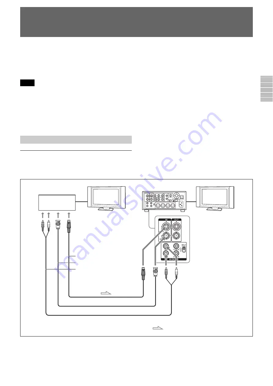
To video equipment without an i.LINK jack 

You can connect the unit to video equipment without an 
i.LINK jack. Use the unit as a recorder as follows.

Connect either an S-video cable or a video cable.

Notes

Connections for Recording

Player

Monitor

HVR-M35 (rear panel)

S-video output

Video output

Audio output

S-video cable (not supplied)

Video cable (not supplied)

Audio cable (not supplied)

: Signal flow

Monitor

Содержание HANDYCAM HVR-M35U

Страница 1: ...290 11 1 Digital HD Videocassette Recorder Operating Instructions Before operating the unit please read this manual thoroughly and retain it for future reference HVR M35U M35N M35E M35P 2008 Sony Corporation ...

Страница 2: ...DV1080i DVCAM and DV Formats 33 Input Output Signals in EE Mode 33 Recording Input Signals and Recording Formats 34 Playback Tape Format and Output Signals 35 Playback 37 Connections for Playback 37 Settings for Playback 39 Playback Procedures 39 Playback Functions 40 Auto Repeat CUSTOM REPEAT 43 EDGE CROP MARKER 45 MARKER BURN 46 Using the Unit as a Videocassette Recorder 47 Connections for Recor...

Страница 3: ...o a Computer 67 Preparations 68 Chapter 5 Adjusting and Setting Through Menus Operating Menus 70 Menu Structure 71 Menu Contents 72 Chapter 6 Maintenance Troubleshooting 86 Warning Indicators and Messages 93 Notes on Use 95 Notes on the Videocassette Recorder 95 Cleaning of the Video Heads 95 Notes on the Video Cassettes 96 Notes on the LCD Screen 97 About Moisture Condensation 97 Digital Hours Me...

Страница 4: ...onnected with HDV compatible televisions or computers DVCAM DV format DVCAM is based on the consumer DV format which uses the 4 1 1 component digital format 60i or the 4 2 0 format 50i and provides a 1 4 inch digital recording format for professional use The unit provides both DVCAM format recording playback and DV format in SP mode recording playback For details see Major Differences among HDV108...

Страница 5: ... a STATUS CHECK button Time code and user bits On the unit you can use both time code and user bits Using the menu these can be set easily The unit can output time code to an external device via the TC OUT jack JOG AUDIO function If you use the optional DSRM 10 remote control unit not supplied audio can be monitored at various playback speeds in jog shuttle mode Jog audio cannot be output when the...

Страница 6: ...ccepts signals from any Sony Remote Commander whose command mode is set to VTR4 To disable control from a Remote Commander set COMMANDER in the OTHERS menu to CONTROL S d ON STANDBY switch and lamp The ON STANDBY lamp lights up in green or red when the POWER switch on the rear panel of the unit is in the position ON Press this switch while the lamp is lit in red in the standby mode to turn the uni...

Страница 7: ...jack 8 and the Speaker qa CH 1 2 channels 1 2 only MIX channels 1 2 and channels 3 4 CH 3 4 channels 3 4 only During audio dubbing if you want to listen to the sound recorded on the tape set this switch to CH 1 2 if you want to listen to the sound being dubbed set the switch to CH 3 4 Only channels 3 and 4 can be used to dub To check the sound to be dubbed before dubbing set this switch to CH 3 4 ...

Страница 8: ...s such as a copyright information signal incorrectly When a signal is input via the HDV DV jack the settings of the menus listed below are unavailable 60i 50i SEL AUDIO MODE AUDIO LOCK AGC CH1 2 AGC CH3 4 INPUT LEVEL 10 2 4 switch in AUDIO IN AUDIO REC LEVEL control knob AUDIO INPUT AUTO MANU FIX switch k Speaker bottom panel Use this speaker to monitor sounds in monaural during recording or playb...

Страница 9: ... k buttons While the STATUS CHECK screen is displayed you can switch the screen by pressing the J j buttons b MENU button Press this button to display the menu list on screen For details on the menus see Operating Menus on page 70 c EXEC execute button Use this button in menu settings d STATUS CHECK button Press this button to check the audio level and menu settings To display the STATUS CHECK scr...

Страница 10: ...s determined by calculation based on the time code that is simple approximation Therefore in cases such as the following the value may be inaccurate There is a portion where the time code is not continuous on the tape you are using The time code in both the drop frame mode and the non drop frame mode are recorded on the tape you are using only for 60i signals including 24p 30p There is a blank por...

Страница 11: ...on executes the function you have set For details on ASSIGN buttons see ASSIGN BTN on page 83 b DUPLICATE button indicator Use this button to duplicate a tape including the time code While duplication is in progress the indicator lights For details on the duplicate function see Duplication Generating a work tape with the same time code on page 61 When the unit is in the stop mode and HDV DV signal...

Страница 12: ...d For details on running speed with SHUTTLEMAX see FF REW SPEED in VTR SET menu on page 80 e PLAY button indicator When you press this button the indicator lights and playback begins If you press this button while holding down the REW button during stop the tape is rewound to its beginning and starts playing automatically during rewind the REW indicator lights and the PLAY indicator blinks When th...

Страница 13: ... volume level which exceeds the dynamic range of the input amplifier If you input a sound at a level that exceeds the acceptable range the recorded sound is distorted b AUDIO REC LEVEL control knobs CH 1 to CH 4 Use these knobs to adjust the levels of the analog audio signals input to the unit for each channel These knobs are enabled only when the AUDIO INPUT AUTO MANU FIX switch 1 is set to MANU ...

Страница 14: ...recording or in EE mode c DV indicator Lights when the unit is in either of the following operating states When a tape recorded in DV format SP mode only is being played back When the following four conditions are met When HDV DV SEL in the IN OUT REC menu is set to AUTO When REC MODE in the IN OUT REC menu is set to DV When DV or DVCAM signals are being input from any of the input jacks During re...

Страница 15: ...e HDV DV jack When a tape that has 1080 50i signals or PAL signals is being played back h 25p indicator Lights when the unit is in either of the following operating states When a tape recorded in 1080 25p format or 720 25p format is being played back When 1080 25p signals are input from the HDV DV jack i HDV i LINK indicator Lights when HDV signals are input output through the i LINK interface j D...

Страница 16: ...3 4 channels 3 4 b AES EBU OUT jacks Outputs digital audio signals in AES EBU format Connect these jacks to input jacks of devices with an AES EBU interface c TC OUT time code output jack Outputs the time code of the unit Connect this jack to a time code input jack on an external device such as a time code reader or a VCR The unit outputs the time code depending on the operating state as follows P...

Страница 17: ...ion Even though the HDV DV jack of the unit is a 6 pin type no power is supplied For details on each setting when HDV DV signals are input see HDV DV SEL page 72 A video signal which is input from the HDV DV jack will be output directly to the HD SD SDI OUT jack the COMPONENT OUT jacks the S VIDEO OUT jack and the VIDEO OUT jack with the jitter of the i LINK signal This jitter may be displayed on ...

Страница 18: ...T jacks You can set the output video format by using SDI CMPNT of VIDEO OUT in the IN OUT REC menu Signals are output to the HD SD SDI OUT jack and COMPONENT OUT jack simultaneously The setting of SDI CMPNT of VIDEO OUT in the IN OUT REC menu is effective for both the HD SD SDI OUT jack and the COMPONENT OUT jack Only signals of EE pictures in HDV format during tape playback or during signal input...

Страница 19: ... for playback stop pause playback as well as the time code tape counter and data status of the unit Jacks labeled CONTROL L have the same function as LANC jacks There are some limitations when you edit an HDV formatted tape Refer to the Notes in Editing Connecting a Computer on page 67 ...

Страница 20: ...ration than if you use the S VIDEO jacks You can set the output video format by using SDI CMPNT of VIDEO OUT in the IN OUT REC menu When the DISPLAY OUTPUT switch is set to ALL text data such as time code menu and alarm messages are superimposed on a monitor connected using the COMPONENT OUT jacks page 25 When images are output in 720p format some of the text image data outer frame underscan porti...

Страница 21: ...ed 75 color bars with 7 5 IRE setup With SMPTE selected in 480i LEVEL of the IN OUT REC menu Y 1 0 Vp p with 0 3 Vp p sync negative output impedance 75 Ω ohms unbalanced Pb Cb B Y Pr Cr R Y 0 7 Vp p output impedance 75 Ω ohms unbalanced 100 color bars with no setup Output with other settings Y 1 0 Vp p output impedance 75 Ω ohms unbalanced Pb Cb B Y Pr Cr R Y 0 7 Vp p output impedance 75 Ω ohms un...

Страница 22: ...92 b AUDIO IN CH 1 to CH 4 jacks Used to input analog audio signals CH 1 to CH 4 During audio dubbing sounds are dubbed onto channels 3 and 4 During audio dubbing use the AUDIO IN CH 3 and CH 4 jacks The AUDIO IN CH 1 and CH 2 jacks cannot be used for audio dubbing c AUDIO OUT CH 1 to CH 4 jacks Used to output audio signals CH 1 to CH 4 To input balanced audio signals via the AUDIO IN jacks use a ...

Страница 23: ...ing begins h REW rewind button i PLAY button j FF fast forward button k STOP button l PAUSE button m DATA CODE button Press this button to display the data codes recording date time For details on data codes see Displaying information data codes recorded on a tape on page 40 n COUNTER SELECT button While the data or time counter is displayed press this button to change the time counter display in ...

Страница 24: ... any Sony Remote Commander with a command mode set to VTR4 To disable control from Remote Commander set COMMANDER in the OTHERS menu to CONTROL S Before using Remote Commander Remove the insulation sheet before using the Remote Commander To change the battery of the Remote Commander 1 While pressing on the tab inset your fingernail into the slit to pull out the battery case 2 Place a new battery w...

Страница 25: ...ter on the data screen by pressing the DISPLAY button when the unit is turned on Data display You can confirm important information for normal recording or playback such as time code or remaining tape time on the screen a Format indicator HDV1080i HDV720p DVCAM or DV SP are displayed b 60i 24p 30p 50i 25p indicator c Repeat indicator Displays a repeat indicator when the TIMER switch is set to REPE...

Страница 26: ... page 42 n Black signal indicator Displays a Black signal indicator when COLOR BAR is set to ON and TYPE is set to BLACK in COLOR BAR of the IN OUT REC menu For details on color bar type see COLOR BAR in the IN OUT REC menu on page 76 o Audio mode indicator During recording in DV mode displays when you select FS32K for AUDIO MODE in the AUDIO SET menu When you select FS48K is displayed During reco...

Страница 27: ...E Selects the size of the time counter COLOR Selects the color of the time counter For details on COUNTER SET see page 77 STATUS CHECK screen To display the STATUS CHECK screen press the STATUS CHECK button Each time you press the J j button the STATUS CHECK screen switches in the order of AUDIO OUTPUT ASSIGN and CUSTOM REPEAT To hide the STATUS CHECK screen press the STATUS CHECK button again Whi...

Страница 28: ... switch is set to AUTO the level meters do not turn red Link symbol When the AGC Auto Gain Control of a pair of channels is linked this symbol is placed between the channels In the EE mode if AGC CH1 2 in the AUDIO SET menu is set to LINKED and the AUDIO INPUT switch is set to AUTO channels 1 and 2 can be linked for AGC operation and for stereo sound where channel 1 is set for the left sound and c...

Страница 29: ...PEAT b REPEAT TIMES displays the times that the tape has played and the total repeat times you have set in REPEAT TIMES c REPEAT CYCLE displays the playback time and the interval time of the tape which you have set in REPEAT CYCLE d START TIME displays the time CUSTOM REPEAT starts which you have set in START TIME e Date and time displays the date and time set by CLOCK SET in the OTHERS menu when ...

Страница 30: ...e specifications are the same as those of home use DV SP tapes The recording time on an HDV tape is also the same as that of a DV SP tape The track pitch of DVCAM is 15 µm which is 1 5 times that of HDV DV SP Therefore the recording time using DVCAM recording on the same tape will be two thirds of the time available when HDV DV SP recording is used Cassette memory Some mini cassettes and standard ...

Страница 31: ...upward then insert it into the unit Do not insert the cassette forcibly The unit may be damaged Do not eject load the cassette in a place subject to light The internal sensor of the unit may operate incorrectly if too much light falls on the unit When inserting a cassette hold the back edge of the cassette in the center and push it until the cassette is inserted deep into the unit If you hold the ...

Страница 32: ...l audio signals in HDV extended format The unit can input output and record signals via the HDV DV jack The unit can play back pictures recorded in 720 24p 720 25p or 720 30p of the HDV format but you cannot input output these pictures via the HDV DV jack The unit cannot input output record or play back a tape recorded in 720 60p or 720 50p of the HDV format and 480p 576p of the SD format For deta...

Страница 33: ...p and 30p with HDV or DV SP format Select the signal input with the INPUT SELECT switch page 8 Analog signal output section a Output No output or N A 1 The format of the picture output from the COMPONENT OUT jacks can be set in SDI CMPNT of VIDEO OUT in the IN OUT REC menu page 73 2 The signals are down converted and output with SD picture quality Major Differences among HDV1080i DVCAM and DV Form...

Страница 34: ... 25p DVCAM format DV SP format a Recordable Not recordable HDV 720 30p 25p 24p signals can be played back but cannot be input output via the HDV DV jack on the unit HDV 720 60p HDV720 50p and SD 480p 576p signals cannot be input output recorded or played back on the unit SDI output 1 i LINK output Digital audio output SDI DV DVCAM DV HDV AES EBU Output signal HD SD SDI OUT HDV DV HDV DV AES EBU OU...

Страница 35: ...p signals can be played back but not input output via the HDV DV jack on the unit HDV 720 60p HDV720 50p and SD 480p 576p signals cannot be input output recorded or played back on the unit Playback Tape Format and Output Signals Analog video output Analog audio output Output signal VIDEO S VIDEO COMPONENT OUT AUDIO OUT 1 3 AUDIO OUT 2 4 Output jack Format of the signals recorded on the tape DV DVC...

Страница 36: ...sion can be changed in DOWN CONV AU of i LINK SET in the IN OUT REC menu page 74 4 24p signals are converted to 60i signals by 2 3 pull down and then output HDV 720 30p 25p 24p signals can be played back but cannot be input output via the HDV DV jack on the unit HDV 720 60p HDV720 50p and SD 480p 576p signals cannot be input output recorded or played back on the unit SDI output i LINK output Digit...

Страница 37: ...bles as shown below For each jack see page 16 When you connect the unit to a monitor compatible with SDI audio using an SDI cable audio cable connection is not needed However when you connect the unit to a monitor incompatible with SDI audio a separate connection using an audio cable is needed Connections for Playback Signal flow Monitor recorder S video input Video input AES EBU input SDI cable n...

Страница 38: ...tors of a monitor a humming noise may be generated or the image may be distorted If these phenomena occur use the INPUT SELECT switch to select a signal that is not being input or disconnect the cables The unit cannot up convert DVCAM DV recordings to HDV at output When SDI CMPNT of VIDEO OUT in the IN OUT REC menu is set to either 1080i 480i or 1080i 576i 1080 24p and 1080 30p video signals playe...

Страница 39: ...5p to 576i respectively Some general consumer television sets are provided with a function to control equipment connected with the i LINK cable Such a function however may not work with the unit Preparation on the unit Text information is superimposed to the VIDEO OUT jack S VIDEO OUT jack COMPONENT OUT jacks and HD SD SDI OUT jack To output video signals without text data set the DISPLAY OUTPUT s...

Страница 40: ...g playback you can check the recording date and time from the data codes by displaying this information on the unit Each time you press the DATA CODE button on the Remote Commander the display switches between no data code display and recording date time display Also you can change the display by setting DATA CODE in the DISPLAY SET menu For details see DATA CODE on page 78 If data codes were not ...

Страница 41: ...utput Button Operation speed Forward direction Reverse direction Forward direction Reverse direction 1 10 One tenth of normal speed 1 3 One fifth of normal speed 1 Playback at normal speed 2 Playback at normal speed FRAME c C Frame by frame forward scanning 8 speed SHUTTLE MAX 24 speed DVCAM DV formatted tape Playback options Operation Play at 1 10 of normal speed Press the 1 10 button during play...

Страница 42: ...earches for the previous or next search point When a search point is located its number is indicated on the monitor screen The unit starts searching backwards or forwards until the number comes to zero then plays back the scene How signals are recorded There are four different signal types one for each search method index title date and photo signals The unit can record either index signals or dat...

Страница 43: ...es Set the number of repeat times by pressing the J j buttons on the unit Press the EXEC button to complete the operation REPEAT CYCLE ON OFF Selects either to enable or disable the REPEAT CYCLE setting CYCLE Sets the time of intervals for playback The time of repeat interval is equal to the total time of tape in playback rewind and stop Repeat intervals can be selected from 15 minutes to 300 minu...

Страница 44: ...nds auto repeat playback starts automatically When the following items on the tape are searched for the unit rewinds the tape to its beginning and starts auto repeat playback automatically Index signals A portion unrecorded A portion recorded in a format set by other than AUTO in HDV DV SEL in the IN OUT REC menu Tape end When START TIME is set to ON Set the TIMER switch to REPEAT When the unit is...

Страница 45: ...AT may not be performed correctly The unit allows you to adjust the edge crop position under the following conditions When you output down converted HDV 16 9 wide screen pictures to 4 3 standard TV mode pictures When you output converted DV 16 9 wide screen pictures to 4 3 standard TV mode pictures By displaying the edge crop marker on the monitor you can check the crop position on the LCD monitor...

Страница 46: ... format are played back or wide screen HDV DVCAM DV signals are input to each VIDEO jack While an HDV signal is input via the HDV DV jack and DOWN CONVERT of VIDEO OUT in the IN OUT REC menu is set to EDGE CROP the marker can not be displayed While a DV signal is input via the HDV DV jack or an SD signal is input via the S VIDEO IN or VIDEO IN jack and DV WIDE CONV of VIDEO OUT in the IN OUT REC m...

Страница 47: ... editing software you use Edit functions are specified by the editing software For details on the editing methods refer to the instruction manual of the editing software For details see also page 67 and 68 To video equipment without an i LINK jack You can connect the unit to video equipment without an i LINK jack Use the unit as a recorder as follows Connect either an S video cable or a video cabl...

Страница 48: ...dio signals are sent without any degradation in quality enabling high quality recording The signal flow is automatically detected so you do not need to make separate connections for input and output When you record video from HDV compatible equipment set HDV DV SEL in the IN OUT REC menu to AUTO To record video from DVCAM DV equipment set HDV DV SEL in the IN OUT REC menu to AUTO or DV before conn...

Страница 49: ... MPEG2 signals except 1080 60i 1080 24p 1080 30p 1080 50i 1080 25p of HDV When you record HDV signals input from the HDV DV jack the connection between the recorded signals pauses for about one second The unit cannot record color bar output in the progressive system Color bar outputs are recorded in 1080 60i or 1080 50i format according to the setting in 60i 50i SEL of the OTHERS menu page 85 Prep...

Страница 50: ...he AUDIO SET menu page 79 FS32K Switches the audio mode to 4 channel mode FS48K Switches the audio mode to 2 channel mode When recording a tape in DV SP you can set AUDIO LOCK in the AUDIO SET menu page 79 When signals are input from the HDV DV jack the audio mode is the same as the one used to input signals from the player To dub audio after recording see page 65 7 Set the INPUT LEVEL switch on t...

Страница 51: ... HDV format for recording Marking an index By pressing the INDEX button on the unit or the INDEX MARK button on the Remote Commander during recording you can mark an index signal at any place on the tape If you mark an index at a scene you want to be able to search for you can easily find the scene later When AUTO INDEX in the VTR SET menu is set to ON if you start recording while the tape is stop...

Страница 52: ... At the preset time the power of the unit turns on automatically and recording starts after a few to several tens of seconds Set the timer allowing a margin for the recording to start You do not need to press the REC button To turn the unit off press the STOP button on the unit to stop the tape transport operation beforehand If you turn the unit off while a tape is running for example by using an ...

Страница 53: ...ime cord may not be displayed properly The a code and user bits cannot be reset on the unit from a Remote Commander equipped with a counter reset function You can set the initial time code value generated by the internal time code generator In addition you can set the user bits to record data such as the date time scene number reel number or other useful information The time data settings are set ...

Страница 54: ... value of the user bits You can set the user bits as eight digit hexadecimal values base 16 to have the date time scene number and other information inserted into the time code track When HDV signals are input from the HDV DV jack the user bits of HDV signals are applied In this case you do not have to follow the procedures below When recording the internal color bars in HDV format user bits can s...

Страница 55: ...less of the HDV DV IN TC setting Bars are recorded as the time code if you start recording when this item is set to EXTERNAL the INPUT SELECT switch on the front panel is set to HDV DV and no signal is input via the HDV DV jack or the software of the editing controller does not output a time code When any signals are input the time code of those signals is recorded When this item is set to EXTERNA...

Страница 56: ... is set to the non drop frame mode If TC MAKE is set to PRESET the mode is also set to the non drop frame mode DF Selects the drop frame mode NDF Selects the non drop frame mode When you set 60i 50i SEL in the OTHERS menu to 50i the unit applies the 50i system specification Therefore the time code generated by the unit during recording is that of the non drop frame mode Even if 60i system signals ...

Страница 57: ...layback Audio dubbing Time code user bits on the tape Playback at various speeds a DUB1 b Time code user bits on the tape when JOG TC OUT is set to ON If set to OFF time codes user bits are not displayed and recorded EE INTERNAL HDV DV Duplicate DUPLICATE1 b Time code user bits of another device connected to the HDV DV jack c Recording Recording Pause REC1 b Time code user bits internally generate...

Страница 58: ...ent are output During recording in 1080 24p the 30 frame rate time codes are output after conversion To output a 1080 24p signal without frame rate conversion of the time code output it from the HDV DV jack without down conversion When JOG TC OUT is set to OFF in EE mode time codes may not be output Time codes via the TC OUT jack are output with the same timing as that of the phase of the output s...

Страница 59: ...Also by connecting the unit to an editing controller via the HDV DV jack you can configure a digital non linear editing system For connections of the editing controller and the unit refer to the editing controller instruction manual Before dubbing you must set the format in which you want to output signals Make HDV DV SEL page 72 and i LINK SET page 74 settings in the IN OUT REC menu For details r...

Страница 60: ...time is the same as the recording time indicated on the DVCAM cassette When progressive HDV signals are played back and down converted into DVCAM or DV format to output to i LINK connection the signals are converted to interlace system 1080 24p and 1080 30p are converted to 480i and 1080 25p to 576i respectively When 4 channel audio HDV signals are played back and down converted into DVCAM or DV f...

Страница 61: ...at and duplicates DV SP The player automatically detects DV SP format and duplicates If the original signal is mixed with other types of signal as you transfer the image to a computer the transfer procedures may be interrupted When transferring an image using a tape dubbed with DUPLICATE PLUS on the unit to a computer we recommend you duplicate it in a single format When non compatible HDV signals...

Страница 62: ...ing on each tape 3 Press the STOP button on the unit 4 While holding the DUPLICATE button down press the PLAY button on the unit The unit enters the duplicate standby mode The player enters the playback pause mode Then the DUPLICATE and PLAY indicators on the unit light and duplication starts To adjust the point where duplication starts while holding the DUPLICATE button down press the PAUSE butto...

Страница 63: ...ips the blank portion automatically reducing the length of the recorded part of the tape The operations of the player and recorder the unit when a blank portion is detected are as follows The unit performs the above operations automatically to reduce the blank portions of a tape during duplication Depending on the specifications the skip function may not work on some players When the unit resumes ...

Страница 64: ...ontrol The player cannot be operated 13 PLAYER Cannot control The player rejects operations 14 PLAYER Cannot control The player is disabled or is in a different mode than the recorder the unit has requested 15 PLAYER Cannot control The player is in an inappropriate condition 16 PLAYER Cannot record due to copyright protection A copyright protected signal is recorded on the cassette in the player t...

Страница 65: ...e of the recorded tape is 32 kHz you can dub the sound regardless of the AUDIO MODE setting in the AUDIO SET menu For details on AUDIO MODE see AUDIO SET menu on page 79 The sound is dubbed only onto channels 3 4 You cannot dub the sound onto channels 1 2 Connection of external devices The following shows an example of a basic connection for audio dubbing When you connect the unit to a monitor inc...

Страница 66: ... in step 7 While looking at the audio level meters on the STATUS CHECK screen turn the AUDIO REC LEVEL control knobs and adjust the recording level Adjust the audio recording level so that the recording level does not exceed 0 dB when the audio signal is at its maximum If the recording level exceeds 0 dB the sound will be distorted 9 Press the PAUSE button The PAUSE indicator goes off and audio du...

Страница 67: ...pped with an i LINK jack and you intend to disconnect or reconnect the i LINK cable turn off the computer and pull out the plug of its power cord from the wall outlet beforehand If you connect or disconnect the i LINK cable while the computer is connected to the AC outlet high voltage current 8 to 40 V is output from the i LINK jack of the device to the unit which may cause a malfunction Before co...

Страница 68: ...ou record HDV signals that are input through the HDV DV jack the connecting portion between scenes on the tape will be displayed as a still picture for approximately 1 second We recommend you perform digital nonlinear editing If your editing software has the capability to output the time code as well as the video and audio signals to the unit and you intend to record that time code set HDV DV IN T...

Страница 69: ...sfer picture data recorded on a tape to an editing machine in HDV page 72 set HDV DV SEL in the IN OUT REC menu to HDV then set HDV t DV CONV of i LINK SET in the IN OUT REC menu to OFF page 74 To transfer picture data to a computer editing machine in DVCAM DV format set HDV DV SEL to DV page 72 Then according to the desired recording format set REC MODE to DVCAM or DV SP page 72 Also according to...

Страница 70: ... the settings of the menu may be changed accidentally If the internal backup battery is exhausted the time set in the internal clock the 60i 50i SEL setting and the time code of the FREE RUN setting will be initialized The internal backup battery is fully charged if you connect the power to the unit for about 24 hours A fully charged internal battery can run for about 1 month Changing a menu setti...

Страница 71: ...LAY page 78 REMAINING page 78 LCD BRIGHT page 78 LCD COLOR page 78 LCD BLACK page 78 AUDIO SET AUDIO MODE page 79 AUDIO LOCK page 79 JOG AUDIO page 79 AGC CH1 2 page 79 AGC CH3 4 page 79 VTR SET DUPLICATE PLUS page 80 CUSTOM REPEAT page 80 AUTO INDEX page 80 STILL PICT page 80 FF REW SPEED page 80 STILL TIME page 81 FROM STILL page 81 FROM REC P page 81 TC UB SET TC PRESET page 81 UB PRESET page 8...

Страница 72: ...ack Also select this setting when the unit is connected via an i LINK cable to a computer supporting HDV format see pages 48 59 DV Outputs signals of portions recorded in DVCAM DV format during tape playback When an i LINK cable is connected only signals in DVCAM DV format from the HDV DV jack are input or output for recording playback Also select this setting when the unit is connected via an i L...

Страница 73: ... image by compressing the image vertically EDGE CROP Maintains the original image size and crops the left and right edges of the images SD SDI SET VIDEO INDEX Sets whether to overlap the aspect ratio and signal format of SD wide signal with VIDEO INDEX or not BON VIDEO INDEX is overlapped OFF VIDEO INDEX is not overlapped RP188 ATC Sets whether to overlap the RP 188 ATC Ancillary Time Code with SD...

Страница 74: ...ortion on the tape the unit counts the blank portion as ATN formatted in DVCAM When using a duplicating function that is equipped with a device such as the DSR 25 45 50 select DVCAM Please note that a duplicated tape and the source tape recorded in HDV format with DVCAM selected do not share the same ATN Time code value is displayed correctly When you change the video format setting of DOWN CONVER...

Страница 75: ...V WIDE CONV of VIDEO OUT or DOWN CONVERT of i LINK SET in the IN OUT REC menu is set to EDGE CROP The edge crop marker is displayed under the following conditions When an HDV formatted tape is played back When HDV signals are input to the HDV DV jack When a DV wide formatted tape is played back When DV wide SD signals are input to the HDV DV jack S VIDEO IN jack or VIDEO IN jack Edge cropped DV wi...

Страница 76: ...y HDV DV SEL and REC MODE When HDV DV SEL is set to AUTO the format of the color bar and tone signals will be output recorded according to the video format displayed in 1 Format indicator page 25 of the text data display on a monitor When HDV DV SEL is set to HDV color bars and tone signals are output recorded in HDV format When HDV DV SEL is set to DV and REC MODE in the IN OUT REC menu is set to...

Страница 77: ...el SMPTE Sets the COMPONENT OUT jacks to SMPTE level For details on COMPONENT OUT jack specifications see page 104 Icon Menu Submenu Setting Note Image Sound Time code REC button EE picture of the input image EE sound of the input sound CH 1 2 a See page 57 DUPLICATE button b Image input to HDV DV jack Sound input to HDV DV jack AUDIO DUB button Mute screen black EE sound of the input sound CH 3 4...

Страница 78: ...lays the date and time when recorded LETTER SIZE Selects the character size of the menu at the cursor BNORMAL Normal size 2 Double height size DATE DISPLAY Selects the date display in the data code display Y M D Displays YY MM DD year month day M D Y Displays MM DD YY month day year Default setting for the HVR M35U M35N D M Y Displays DD MM YY day month year Default setting for the HVR M35E M35P T...

Страница 79: ...mat the menu is set to LOCK MODE During i LINK input the same setting as that of the input signal is selected regardless of this setting JOG AUDIO page 42 Selects either to turn the sound output on or off when the tape is played at a speed other than normal Available in DVCAM DV format only BOFF Does not output the sound when playing a tape at a speed other than normal ON Outputs the sound when pl...

Страница 80: ...he EXEC button REPEAT CYCLE ON OFF Selects whether to apply the REPEAT CYCLE setting or not CYCLE Sets the time of intervals for playback Set the number by pressing the J j buttons and then press the EXEC button START TIME ON OFF Selects whether to apply START TIME setting or not TIME Sets the starting time of CUSTOM REPEAT Set the number by pressing the J j buttons on the unit To switch between h...

Страница 81: ...or more than 3 minutes BSTOP Stops the tape REC PAUSE Maintains the recording pause mode When the recording pause mode continues for a long time after you select REC PAUSE the tape may be damaged or the video heads may be damaged or clogged If there is no other reason to do otherwise select STOP Particularly when you use a Mini DV cassette that is longer than 60 minutes select STOP Icon Menu Subme...

Страница 82: ...me code may be somewhat off If the internal backup battery is exhausted the time code of the FREE RUN setting is initialized TC MAKE page 55 Selects the time code when you start recording BREGENERATE The time code value is set to continuous time code from the one already recorded on the tape If no time code is recorded on the tape it starts from 00 00 00 00 PRESET The time code starts from the val...

Страница 83: ... for each ASSIGN button can not be assigned to other ASSIGN buttons If you assign other functions and will be displayed on the left corner of the Data display screen LANGUAGE You can select the desired language on the Data display screen You can choose Simplified English if your native language is not available among the options COMMANDER page 24 Selects the control device BWIRELESS Enables operat...

Страница 84: ...puts sounds from the speaker only and disables beeps ON BEEP Outputs beeps and emits no sounds from the speaker OFF Disables beeps and does not output sounds from the speaker CLOCK SET 1 Press the J j buttons to adjust the number then press the K k buttons to set the month day hour and minute 2 Press the EXEC button to execute 12 00 AM stands for midnight and 12 00 stands for noon when TIME DISPLA...

Страница 85: ...R profile is saved PROFILE NAME Rename a VCR profile already saved 1 Select the VCR profile you want to rename by pressing the J j button and press the EXEC button PROFILE NAME screen is displayed 2 Select a character by pressing the J j K k button on the profile name screen and press the EXEC button Repeat this operation to enter the new name Each name can be up to 12 characters long Characters t...

Страница 86: ...ug while adjusting the menu or the brightness of the LCD monitor The unit operates by itself COMMANDER in the OTHERS menu is set to WIRELESS and a Sony Remote Commander with its command mode set to VTR4 is operating near the unit t Set COMMANDER to CONTROL S When TIMER switch is set to REPEAT and START TIME of CUSTOM REPEAT in the VTR SET menu is set to ON the unit starts to repeat playback at the...

Страница 87: ...s Symptom Cause Remedy The power cannot be turned on The AC power cord is disconnected t Connect the AC power cord The KEY INH switch is set to ON t Set the switch to OFF The POWER switch on the rear of the unit is in the a position OFF t Press the marked side of the POWER switch ON The unit will not operate even if the power has been turned on The KEY INH switch is set to ON t Set the switch to O...

Страница 88: ...the unit play back a tape recorded in LP mode of the DV format t The unit can play back only tapes recorded in the HDV DVCAM format or in SP mode of the DV format A tape recorded in LP mode of the DV format cannot be played back on the unit A picture input via the HDV DV jack is not displayed t Reconnect the i LINK cable not supplied The INPUT SELECT switch is set to a position other than HDV DV t...

Страница 89: ...f the input i LINK signal is not recorded The i LINK signal output from the digital non linear editing controller does not include a time code t Confirm that the editing software you are using is capable of outputting a time code The INPUT SELECT switch is not set to HDV DV t Set it to HDV DV After playing at 1 10 of normal speed in forward or reverse for more than 1 minute normal playback forward...

Страница 90: ...software and consult their manufacturers Although the i LINK cable is connected the image from external equipment is not displayed t Disconnect and then reconnect the i LINK cable correctly The INPUT SELECT switch is set to a setting other than HDV DV t Set it to HDV DV No image is displayed even though the video cable is connected correctly There are output restrictions for some SDI CMPNT setting...

Страница 91: ...N OUT REC SDI CMPNT 480i 576i 480p 480i 576p 576i ALLSCAN MODE in DISPLAY SET ON Recording Dubbing Symptom Cause Remedy Whenever you connect the unit to an AC outlet the unit automatically starts recording The TIMER switch is set to REC t When the TIMER switch is set to REC the unit starts recording whenever the power is connected Set the TIMER switch to OFF Even though the KEY INH switch is set t...

Страница 92: ...ed tape recorded in the 32 kHz audio mode 4 channel If the unit detects the following audio dubbing will automatically abort an alarm message will be superimposed on the LCD monitor and on an external monitor A blank portion A section recorded in other than 32 kHz audio mode 4 channel A portion recorded in other than DVCAM format You have tried to dub the sound onto channels 1 and 2 t Only channel...

Страница 93: ...ensation has occurred Remove the cassette and insert it again after approximately 1 hour page 97 C 22 ss t The video head is dirty Use a cleaning cassette to clean the head page 95 C 31 ss C 32 ss t Symptoms other than the above are occurring Insert the cassette again and retry the operation Do not take this action however if there is any condensation at all in the unit page 97 t Unplug the power ...

Страница 94: ...Cannot add audio INPUT SELECT is set to HDV DV Not recorded in DVCAM mode Cannot add audio Cannot add audio You cannot add audio unless the recorded audio format is 32 kHz 4 channel 12 bit Make sure that 60i 50i SEL in the OTHERS menu is set correctly Cannot add audio on the blank portion of a tape HDV recorded tape Cannot add audio Cannot add audio HDV DV SEL is set to HDV Others Cannot record du...

Страница 95: ... with a mild detergent solution and finish it with a dry cloth Do not put magnetic objects close to the unit Magnetic fields may damage the recording To prevent electromagnetic interference caused by radio communication equipment such as cellular phones transceivers etc The use of radio communication equipment such as cellular phones or transceivers near the unit may cause a malfunction and can af...

Страница 96: ...dust or sand Leaving a tape in the unit for a long time Cleaning cassettes are replaceable After using the supplied cleaning cassette for the specified number of times buy a replacement cleaning cassette After prolonged use the video heads may become worn out If optimum picture quality is not restored even after you have cleaned the video heads with the cleaning cassette the video heads may have w...

Страница 97: ...rectly from a cold to a warm location moisture may condense inside or outside the unit or tape If you use the tape or video heads in this condition the tape may adhere to the head drum and the video heads or the tape may be damaged or a malfunction may occur When condensation occurs the alarm messages Z Moisture condensation Eject the cassette or Moisture condensation Turn off for 1H appears Moist...

Страница 98: ...ous settings regardless of power on and power off status The rechargeable battery is charged as long as the unit is operated If the period the unit is operated is short the battery discharges gradually and if it is not used at all for approximately 1 month the battery will discharge completely In that case charge the battery and then start using the unit If you do not need to record the date and t...

Страница 99: ...editing of a tape may be restricted for some dubbing methods Read Chapter 4 Dubbing to Other Equipment Using the i LINK Jack Duplication Audio Dubbing and Connecting a Computer before dubbing a tape Some editing software can correctly edit even a tape created in LOCK MODE In that case select LOCK MODE if required Recording tapes used when the unit serves as a recorder Setting independent Input sig...

Страница 100: ...r i LINK output when the unit is used as a player When you play back a tape employing a copy protection signal on the unit you cannot record images from the unit to other equipment You cannot up convert DVCAM DV format to HDV format on the unit During playback in HDV if DV SP is selected from HDV t DV CONV in i LINK SET AUDIO MODE is fixed to UNLOCK MODE When you play back a tape in DVCAM or DV fo...

Страница 101: ...ent may play back a DVCAM formatted tape however the contents cannot be guaranteed Therefore even though you use a proper DVCAM formatted tape for playback and the unit dubs and creates a DVCAM formatted tape the time code may be partially different from the time code format specified as DVCAM on other DV video equipment You cannot use the unit to record video and audio recorded with copyright pro...

Страница 102: ...ay vary from the indicated value when the unit is connected to equipment with a different maximum baud rate What is Mbps Mbps stands for megabits per second or the volume of data that can be sent or received in 1 second For example a baud rate of 100 Mbps means that 100 megabits of data can be sent in 1 second To use the i LINK functions of the unit For details on how to perform dubbing when the u...

Страница 103: ...6DM Approx 63 min using PHDVM 63DM AUDIO jacks Analog audio input AUDIO IN Pin jack 4 10 2 4 dBu Impedance Minimum 47 kΩ kilo ohms unbalanced Maximum input level 10 18 dBu approx 6 Vrms 2 24 dBu approx 12 5 Vrms 4 30 dBu approx 25 Vrms Analog audio output AUDIO OUT XLR type 3 pin convexity 4 4 dBu 600 Ω ohms loading Low impedance balanced MONITOR AUDIO Pin jack 1 Impedance Maximum 1 kΩ kilo ohms O...

Страница 104: ...setup 480i 480p Y with 0 3 Vp p sync negative 1080i 720p Y Pb Pr with 0 6 Vp p 3 level sync HDV DV jack i LINK IEEE 1394 6 pin connector S100 HD SD SDI OUT jack BNC type 1 SD SDI SD SDI format SMPTE259M C 270Mbps HD SDI HD SDI format SMPTE292M AES EBU OUT jack BNC type 2 AES 3id 1995 TC OUT jack BNC type 1 2 2 Vp p 600 Ω ohms 1 2 Vp p 75 Ω ohms 0 5 to 4 Vp p through output 600 Ω ohms Remote contro...

Страница 105: ...ting parts and controls Mass Approx 4 4 kg 9 lb 12 oz Supplied accessories Remote Commander 1 Power cord 1 Cleaning cassette 1 Operating Instructions 1 Design and specifications are subject to change without notice 175 7 212 8 3 8 380 7 15 88 3 1 2 10 13 32 8 7 11 32 9 6 13 32 284 11 1 4 Unit mm inches ...

Страница 106: ...K output 100 S VIDEO VIDEO jack 99 DUPLICATE button 11 DUPLICATE PLUS mode 61 Duplication 61 Detecting a blank portion 63 Series of tapes 63 Warning message 64 DV cassette 30 DV format 4 33 DVCAM cassette 30 DVCAM format 4 33 E EDGE CROP MARKER 45 Editing 67 Transferring from a computer 69 Transferring to a computer 68 EE mode 9 EJECT button 32 END SEARCH button 24 EXEC button 9 F FF button 12 Fra...

Страница 107: ...at 33 during recording 34 Remaining tape time 26 Remote Commander 23 REPEAT CYCLE 43 REPEAT TIMES 43 RESET button 18 Counter reset 10 REW button 12 REW PLAY button 23 S S VIDEO jack 20 Scheduled maintenance 98 SDI 5 Search 42 SEARCH SELECT button 23 Self diagnosis 93 SHUTTLE MAX button 24 SPEAKER 8 Speaker LEVEL control 7 Specifications 103 START TIME 43 STATUS CHECK button 9 STATUS CHECK screen 2...

Страница 108: ... CODE 78 DATE DISPLAY 78 DUPLICATE PLUS 80 E EE PB SEL 77 F FF REW SPEED 80 FROM REC P 81 FROM STILL 81 H HDV DV IN TC 82 HDV DV SEL 72 HOURS METER 84 I i LINK SET 74 INITIALIZE 85 J JOG AUDIO 79 JOG TC OUT 82 L LANGUAGE 83 LCD BLACK 78 LCD BRIGHT 78 LCD COLOR 78 LETTER SIZE 78 M MARKER BURN 78 P PB CNR 84 PB YNR 84 R REC MODE 72 REMAINING 78 S SPEAKER BEEP 84 STILL PICT 80 STILL TIME 81 T TC FORM...

Страница 109: ......

Страница 110: ......

Страница 111: ......

Страница 112: ...Printed in Japan Printed on 70 or more recycled paper using VOC Volatile Organic Compound free vegetable oil based ink GB ...

Отзывы: