background image

Pre

par

at

ion

Supplied Accessories

8

Preparation

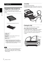
Supplied Accessories

The unit is packed together with the following 
accessories. Check that nothing is missing from your 
package.

Notes

• Retain the original carton and packing materials in 

case you have to transport the unit in the future.

• Keep the supplied floppy disk, since it is required 

when repairing. 

Assembly

Insert the film tray into the unit.
Holding both sides of the film tray and tray cover with 
both hands, insert the film tray all the way into the unit.

Placing the Unit

You can place the unit horizontally or vertically.

When placing the unit horizontally

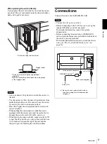
To maintain performance, adequate space is needed for 
ventilation. Also, to remove jammed film, space of 
about 11 cm (4 3/8 inches) towards the back and about 
26 cm (10 1/4 inches) over the top of the unit are 
required.

Film tray (1)

AC power cord (1) 

a)

Cleaning kit (1)
Stopper sheet (1)
Ferrite cores (2)
Warranty card (1) (for the customers in the U.S.A. and 
Canada only)
CD-ROM (Instructions for Use disk) (1)
Floppy disk (1)
Operation Guide (1) 

a) Footnote for the customers in the U.S.A and Canada

When you use the printer in the U.S.A. or Canada, use the 
AC power cord supplied. When you use the printer in a 
country other than the U.S.A. or Canada, use the proper 
AC power cord for your local power system.

Casters for vertical placement of the unit (2

)

21 cm 
(8 5/8 inches)

11 cm 
(4 3/8 inches)

26 cm 
(10 1/4 inches)

Содержание film imager

Страница 1: ...anual Page 31 This manual is comprised of the Instructions for Use and the Setup Manual The Instructions for Use gives the information on how to use the printer for the routine work The Setup Manual gives the system administrator the information needed to setup the printer and connect it to the network ...

Страница 2: ...cables to comply with FCC emission limits For the customers in Canada This unit has been certified according to Standard CSA C22 2 NO 601 1 For the customers in the U S A and Canada Model UP DF500 is Non Patient Equipment This unit can not be used in the vicinity of patients Patient Vicinity Important safeguards notices for use in the medical environments 1 All the equipments connected to this uni...

Страница 3: ...chieved when the equip ment is connected to an equivalent receptacle marked Hospital Only or Hospital Grade Voor de Klanten in Nederland Dit apparaat bevat een vast ingebouwde batterij die niet vorvangen hoeft te worden tijdens de levensduur van het apparaat Raadpleeg uw leverancier indien de batterij toch vervangen moet worden De batterij mag alleen vervangen worden door vakbekwaam servicepersone...

Страница 4: ...Film 11 Loading Film 11 Printing 14 Adjustment Menu Operation 15 Confirming Information 15 Adjusting the Print Quality 15 Calibrating the Printing Density 16 Adjusting the Tone 17 Selecting a Gamma Curve 19 Miscellaneous Precautions 20 Safety 20 Installation 20 Transporting the Unit 20 Cleaning the Cabinet 20 Maintenance 20 Specifications 24 Messages 25 Error Messages 25 Other Messages 26 Troubles...

Страница 5: ...his manual you will find references to other sections of the manual that contain related information Important note Be sure to read the sections marked They explain points that you should be aware of to operate the unit correctly and prevent malfunctions System Overview The UP DF500 digital film imager is a thermal printer designed to reproduces image data in DICOM format sent via the network The ...

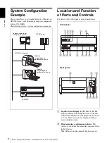
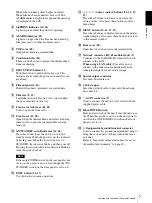
Страница 6: ...n parentheses A Liquid Crystal Display LCD 14 15 25 26 Displays messages showing the status of the unit Operational information is displayed when the unit is in use Error messages are displayed when an error condition occurs B Film remaining confirmation indicator 11 Allows you to check the remaining amount of film in the film tray When films are loaded enough Lights in green Personal computer for...

Страница 7: ...cator is blinking turns the power back on Note If the main POWER switch on the rear panel is not set to on the power is not on even though the ON STANDBY switch on the front panel is set to on M EXEC button 16 17 Use this button in menu operations N G g F f Cursor control buttons 15 16 17 19 Press these buttons to increase or decrease the setting values Also press these buttons to select menu item...

Страница 8: ...it horizontally To maintain performance adequate space is needed for ventilation Also to remove jammed film space of about 11 cm 4 3 8 inches towards the back and about 26 cm 10 1 4 inches over the top of the unit are required Film tray 1 AC power cord 1 a Cleaning kit 1 Stopper sheet 1 Ferrite cores 2 Warranty card 1 for the customers in the U S A and Canada only CD ROM Instructions for Use disk ...

Страница 9: ...than 8 cm 3 1 4 inches between the top of the unit and the subject to prevent blocking the ventilation holes Connections Connect the unit to the 100BASE TX LAN Notes Connect the AC power cord last Before connecting to the LAN be sure to set up the required IP address and sub net mask For detailed information consult the system administrator Before connecting the unit using a 100BASE TX cable attac...

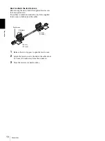
Страница 10: ...o confirm to radiation standards attach the supplied ferrite cores to both ends of the cable 1 Release the two stoppers to open the ferrite core 2 Attach the ferrite cores to the end of the cable about 12 5 mm 1 2 inch away from the connector 3 Close the ferrite core until it clicks 12 5 mm 1 2 inch 12 5 mm 1 2 inch Ferrite core Stoppers ...

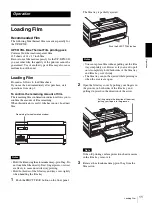
Страница 11: ...e aluminum damp proof bag Do not touch the film directly Dust finger prints or sweat are likely to cause unsatisfactory printing Hold both sides of the film tray and tray cover tightly when handling the film tray 1 Push the EJECT TRAY button on the front panel The film tray is partially ejected Notes You can replace film without pulling out the film tray completely out However if you want to pull ...

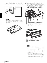
Страница 12: ... or sweat are likely to cause unsatisfactory printing Load the film so that it lays flat in the film tray If the film is curled it will overflow the film tray and the printing position may shift Also it may cause film jamming If you place the film in the film tray with its printing surface facing up it is recommended that you clean the thermal head with the cleaning kit supplied See To clean the t...

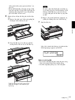
Страница 13: ...y Note Be sure to check that the hooks of the film tray cover and its magnets are attached firmly on the film tray If the film tray cover is not closed correctly film placed in the film tray may slide around 3 Remove the seal from the film completely by pulling the blank portion out of the film tray 7 Insert the film tray After a few seconds the film tray is locked and the following message appear...

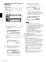
Страница 14: ...he message REMOVE PRINTS may appear even if the number of printouts less than 30 has accumulated depending on the usage environmental condition Do not put the printout which has been removed from the film output slot back inside the film output slot This may cause film jamming If the unit does not print When an error message is displayed in the LCD the unit does not print Take remedies according t...

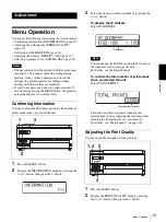
Страница 15: ...ou can confirm the IP address and the total number of prints made since you started the unit 1 Press the MENU button 2 Display the INFORMATION menu by pressing the F or f button then press the g button 3 Select the item you want to confirm by pressing the F or f button To display the IP address Select IP ADDRESS Note You can change the IP address using the browser on the computer used to manage th...

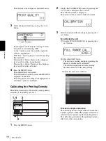
Страница 16: ...utomatically calibrates the printing density according to the density curve set 1 Press the MENU button 2 Display the CALIBRATION menu by pressing the F or f button then press the g button The calibration menu is displayed The unit enters the automatic calibration mode 3 Select the desired calibration type by pressing the F or f button To calibrate the unit 1 Display FULL RANGE CAL by pressing the...

Страница 17: ...ENU button The unit returns to standby status and READY is displayed on the LCD Adjusting the Tone You can adjust the high tone dark areas of the images and the low one light areas of images 1 Press the MENU button 2 Display the DENSITY ADJ menu by pressing the F or f button then press the g button The unit enters the automatic tone adjustment mode 3 Display PATTERN PRINT by pressing the F or f bu...

Страница 18: ... way the dark areas of images will be printed 1 Display SELECT POINT 5 by pressing the F or f button 2 Select the number of the desired high tone area dark area data 5 The high tone range is between 51 and 99 60 70 80 and 90 are skipped Chart of the low tone range The next lightest part The lightest part The outside tone of each box on the cart is changed in the upper and lower direction on the ch...

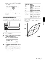
Страница 19: ...re set you cannot change these settings The gamma curves for USER 6 to USER 10 can be set to the desired value For advice on the settings contact your nearest Sony dealer Gamma curve The gamma curves of SONY 1 to SONY 5 are shown below Display the selected number 3 1 2 4 Gamma curve Meaning SONY 1 Default setting SONY 2 The half tone is darker compared to SONY 1 SONY 3 The half tone is lighter com...

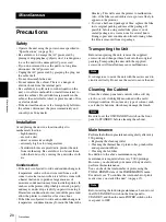
Страница 20: ... film is subjected to wide and sudden changes in temperature condensation may form on the film in the film tray This will cause the printer to malfunction Also if the film is used in this state spots are likely to appear on the printout To store a half used package of film replace the film in its original packing and reseal the package If possible before using sealed film place it in its sealed pa...

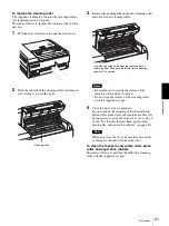
Страница 21: ... of the cleaning roller with the supplied wet pad 4 Close the front cover completely If you continue the cleaning of the thermal head platen roller pinch roller and separation rubber it is not necessary to close the front cover Go to step 2 of the To clean the thermal head platen roller pinch roller and separation rubbers on page 21 Note When you close the cover be careful not to catch your finger...

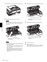
Страница 22: ...l head is still very hot just after printing is finished be careful not touch the thermal head Touching the hot thermal head may cause a burn 3 Wipe the platen roller black rubber roller gently 4 Wipe the pinch roller dark blue rubber roller 5 Close the front cover 6 Remove the film tray You can remove the film tray without pushing the EJECT TRAY button when the power is off Wipe the surface of th...

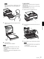
Страница 23: ...Do not use the wet pad used for wiping rollers to clean the thermal head To clean the filters Ventilation holes are provided on the unit to prevent it from overheating Three filters are provided on the front cover for covering the ventilation holes To clean the filters proceed as follows 1 Pull the lock lever to open the front cover 2 Lift the filters upward a little and pull it toward you to remo...

Страница 24: ... 4 oz Printing system Thermal printing Resolution 12 59 dot mm 320dpi Gradations 4 096 levels Maximum print size 401 8 335 4 mm Picture elements 4 224 5 060 dots w h Printing time Approx 70 sheets hour excluding the time for cooling the head Digital interface Network port 1 RJ 45 Modular jack Conforming to 100BASE TX standard Special output connector 1 Input connector AC IN for power Accessories s...

Страница 25: ... Session SOP Class 1 2 840 10008 5 1 1 1 Basic Film Box SOP Class 1 2 840 10008 5 1 1 2 Basic Grayscale Image Box SOP Class 1 2 840 10008 5 1 1 4 Print SOP Class 1 2 840 10008 5 1 1 16 Basic Annotation Box SOP Class 1 2 840 10008 5 1 1 15 Error messages Possible causes and remedies SET FILM The film sheets have run out tLoad the film into the film tray page 11 SET TRAY The film tray is not install...

Страница 26: ...E M nn Mechanical trouble has occurred in the motor system of the unit tTurn off the power once and then turn it on The unit may operate correctly However if the message still remains on the LCD turn off the power immediately and contact your Sony dealer MECHA TROUBLE U nn Mechanical trouble has occurred in the unit system of the unit tTurn off the power once and then turn it on The unit may opera...

Страница 27: ...ray out without pushing the EJECT TRAY button Note When you pull out the film tray hold both sides of the film tray and the tray cover with both hands Note If any printouts have been ejected onto the film tray remove them first before removing the film tray 2 Remove the film jammed around the sepration rubbers 3 Re insert the film tray as it was When messages from J1 to J6 appear 1 Open the cover ...

Страница 28: ...d When the top and the front covers are opened When the front cover is opened When the top and inner covers are opened 2 Close the opened cover firmly The following message appears on the LCD Wait until the message disappears When the unit enters standby status the following message appears ...

Страница 29: ...he inside of the unit 3 Re insert the film tray as it was When REMOVE FILM SOME PLACES J8 Several film sheets have jammed Open all of the covers rear front top and inner covers and check the location of the jammed film Since there may be a film sheet jammed around the film tray pull the film tray out and check for the jammed films ...

Страница 30: ...aning the filters 23 cleaning the pinch roller 22 cleaning the platen roller 22 cleaning the separation rubbers 23 cleaning the thermal head 22 replacing the cleaning roller 21 Menu items CALIBRATION 16 DENSITY ADJ 17 GAMMA SEL 19 INFORMATION 15 PRINT QUALITY 15 Messages error messages 25 other messages 26 P Placing the unit horizontally 8 vertically 9 Precautions condensation 20 installation 20 s...

Страница 31: ...erview 32 Requirements 32 IP Address 33 Setup Setting up the Personal Computer to be Used for Setup 34 About the Setup Window 34 Opening the Setup Window 34 Components of Pages 35 Setup of the Unit 37 Setup of E Mail 37 Confirmation After Setup 38 ...

Страница 32: ...e connected to the network connector of the UP DF500 Operating system a Microsoft Windows 95 Windows 98 Windows NT 4 0 Windows 2000 or Windows XP LAN cable 100BASE TX cross cable Web browser software Internet Explorer a 5 5 or later or Netscape a 4 or later Set the Web browser software as follows No proxy A blank page is opened when the Web browser software is started a Microsoft Windows Windows N...

Страница 33: ...istrator The IP address the UP DF500 will use on the network Sub net mask of the network Gateway address if a gateway is included in the network To confirm the IP address The IP address assigned to the UP DF500 can be confirmed 1 Turn the UP DF500 on 2 Press the MENU button 3 Display INFORMATION on the LCD by pressing the F or f button and then push the g button 4 Display IP ADDRESS on the LCD by ...

Страница 34: ...o be used for setup using the network cross cable About the Setup Window The UP DF500 can be set up on the setup window displayed on the Web browser of the personal computer to be used for setup The setup window has the following pages Summary Print Job page Displays the summary and print job status of the UP DF500 DICOM Settings page Sets up the IP address DICOM AE title and so on Printer Status ...

Страница 35: ...TCP IP section Setup Software Version Displays the version of the setup window IP Address Sets the IP address and displays it Sub net Mask Sets the Sub net mask and displays it Default Gateway Sets the default gateway and displays it B Printer section DICOM Software Version Displays the version of the DICOM software DICOM Software Serial Displays the serial number of the DICOM software AE Title Se...

Страница 36: ...ints after the thermal head has been replaced Lifetime print count Displays the total prints since the unit has been shipped C Printer Media Information display area Vendor ID Model Name Version Number Media Type Media Size Pixel Matrix Resolution Maximum Density Minimum Density Displays various information on the unit status Film Remaining Displays approximate number of film sheets remaining in t...

Страница 37: ...re saved Setup of E Mail The E Mail settings page allows you to set up E mail service so that an e mail message will be sent automatically when an error occurs in the UP DF500 1 Open the E Mail settings page For detailed information on how to open the page see Opening the Setup Window on page 34 2 Set criteria determining when an e mail message should be sent Place the check marks on the check box...

Страница 38: ...he unit starts printing When the image data is not sent Check whether or not the IP address of the modality side is correct When setting up an E mail Confirm the settings for an E mail as follows 1 Click E mail settings in the page selection area to open the E mail settings page When this page is opened after E mail settings have been completed the Send a test E Mail button appears 2 Click the Sen...

Страница 39: ...Sony Corporation ...
Отзывы: