Sony FE 1.4 / 85 GM Скачать руководство пользователя страница 39

2-3

SEL85F14GM (FE 1.4 / 85 GM) (FE 85mm F1.4 GM)

HELP

取り付け時の注意や,グリス塗布方法などを記載しています。
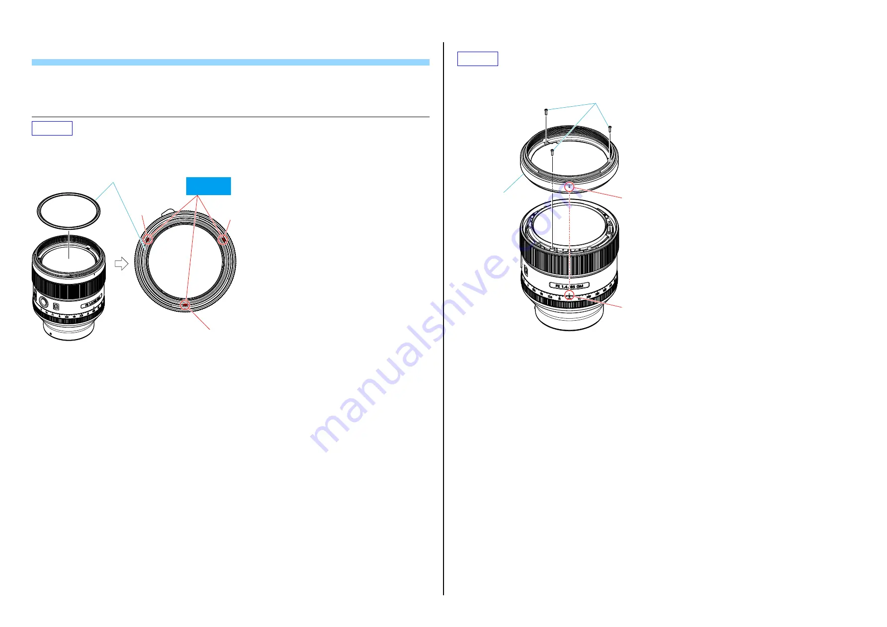
HELP01

ボンド(

B-10

: J-6082-612-A

1. GD

防滴ゴム(

9139

)を取り付け

3

箇所にボンド(

B-10

)を塗布する。

GD防滴ゴム (9139)

ボンド(B-10)
を塗布

HELP02

1. 

フィルターネジ環

ASSY

9139

)の指標と絞り値目盛りの位置を合わせて取り付ける。

2. 

ネジ

3

本で取り付ける。

フィルターネジ環

ASSY (9139)

ネジ

指標

絞り値目盛り

Содержание FE 1.4 / 85 GM

Страница 1: ...6 02 Official Release 1 1 2016 03 Revised 1 A1 15 146 Change of ADJUSTMENT English Page 4 1 Japanese Page 4 1 Yes 1 2 2016 07 Revised 2 A2 15 190 Revision of DISASSEMBLY English Page 2 1 2 2 2 4 2 12 Japanese Page 2 1 2 2 2 4 2 12 Revision of ADJUSTMENTS English Page 4 1 Japanese Page 4 1 Yes SEL85F14GM FE 1 4 85 GM FE 85mm F1 4 GM Ver 1 2 2016 07 US Model Canadian Model AEP Model Chinese Model Ja...

Страница 2: ... sensor 2 Angle of view 1 is the value for 35mm cameras and angle of view 2 is the value for Interchangeable Lens Digital Cameras equipped with an APS C sized image sensor 3 Minimum focus is the distance from the image sensor to the subject Included items The number in parentheses indicates the number of pieces Lens 1 Front lens cap 1 Rear lens cap 1 Lens hood 1 Lens case 1 Set of printed document...

Страница 3: ...ensure that no wires are pinched or contact high wattage resistors 3 Look for unauthorized replacement parts particularly transistors that were installed during a previous repair Point them out to the customer and recommend their replacement 4 Look for parts which through functioning show obvious signs of deterioration Point them out to the customer and recommend their replacement 5 Check the B vo...

Страница 4: ...n a flexible board straight fully into the connector until it reaches the end inside Fig 1 Fig 2 Fig 3 OK The flexible board was plugged in straight and completely NG The flexible board was plugged in crooked NG The flexible board was not plugged in completely Flexible Board Flexible Board Connector Connector Reference line Flexible Board Connector Connector Flexible Board Reference line Connector...

Страница 5: ...ht Fixed Barrel 9139 3rd Group Assy 9139 X Stator Screw Ring 9139 XK Pressure Spring XL Pressure Plate 9139 XM SSM Adjustment Washer F Plate Sheet FB Stator Assy B FT Stator Holder Screw 9139 FE Stator Holder 9139 FG Rotor FH Rotor Rubber Y FI Steel Ball Holding 9139 Outer Assy Service 9139 FL Steel Ball 2 5 FM 2nd Group Assy 9139 S F Spring Washer 9139 SB Dummy Frame 9139 ST Front Holder Barrel 9...

Страница 6: ...ection Rubber GD 9139 and apply the adhesive bond B 10 to three grooves Protection Rubber GD 9139 Groove Groove Groove Apply the adhesive bond B 10 HELP02 1 Match the index of Filter Screw Barrel Assy 9139 and the aperture value scale and attach the Filter Screw Barrel Assy 9139 2 Tighten three screws Filter Screw Barrel Assy 9139 Screws Index Aperture value scale ...

Страница 7: ...A 1 Match the hole of the GD Lens Barrel Assy 9139 and the hole of the 1st Group Assy 9139 and attach the GD Lens Barrel Assy 9139 2 Attach the Back Adjustment Washer Note Attach the same quantity as the attached washers 3 Attach the GD Washer 9139 with screws 4 Apply the adhesive bond B 10 to the screw head 5 Apply the adhesive bond B 110 to the specified locations of the GD Lens Barrel Assy 9139...

Страница 8: ... 10 HELP06 Grease G 85 J 6082 626 A 1 Apply the grease G 85 to the specified locations of Rear Barrel Assy 9139 Rear Barrel Assy 9139 Apply the grease G 85 Apply the grease G 85 2 Attach the Iris Ring Spacer 9139 to the Rear Barrel Assy 9139 and apply the grease G 85 to the specified locations Rear Barrel Assy 9139 Iris Ring Spacer 9139 Rear Barrel Assy 9139 Apply the grease G 85 HELP07 Grease G 8...

Страница 9: ... Assy 9139 Apply the grease G 345 Outer Assy 9139 Apply the grease G 345 Apply the grease G 345 4 Attach the Steel Ball 2MM to the Iris Ring Assy 9139 Steel Ball 2MM Iris Ring Assy 9139 5 Move the slider to the marked 6 Match the 1 4 of Iris Ring Assy 9139 and the index and attach the Iris Ring Assy 9139 At that time the slider is fit into the groove of the Iris Ring Assy 9139 Iris Ring Assy 9139 ...

Страница 10: ...x portion of the CL 1040 board and attach it to the Outer Assy Service 9139 Install the Flexible Board Stator Assy B as shown in the figure below CL 1040 Board Flexible Board Stator Assy B Hole Convex portion Flexible Board Stator Assy B HELP09 Adhesive bond B 10 J 6082 612 A 1 Pass the Main FPC Assy 9139 through the small hole of Outer Assy Service 9139 2 Pass the Flexible Board Stator Assy B thr...

Страница 11: ...e MR Encoder 1740 MR Encoder 1740 Apply the grease G 85 All circumference HELP12 1 Attach the Main FPC Assy 9139 with five claws and the hook 2 Connect the GMR Flexible Assy to the connector of Main FPC Assy 9139 and attach it to the hook Hook Hook Claw Claw Main FPC Assy 9139 GMR Flexible Assy Connector Main FPC Assy 9139 HELP13 Adhesive bond B 10 J 6082 612 A Grease FT 210 9 913 200 37 1 Apply t...

Страница 12: ...adhesive bond B 10 to the groove of Sta tor Screw Ring 9139 which is not affected the groove of Straight Fixed Barrel 9139 OK NG Straight Fixed Barrel 9139 Stator Screw Ring 9139 Stator Screw Ring 9139 Groove 4 locations Stator Screw Ring 9139 Apply the adhesive bond B 10 HELP14 1 Match the Flexible Board of Stator Assy B to the groove of Straight Fixed Barrel 9139 and attach the Stator Assy B Fle...

Страница 13: ...d Stator Holder Screw 9139 Stator Holder 9139 Rotor Rotor Rubber Y Stator Holder Screw 9139 Wide groove Wide convex portion 2 Apply the adhesive bond B 10 to the specified locations Apply the adhesive bond B 10 Straight Fixed Barrel 9139 Narrow groove Wide groove HELP16 1 Attach the Flat Plate 9139 to the Cam Barrel 9139 Cam Barrel 9139 Flat Plate 9139 ...

Страница 14: ... Wide concave portion HELP17 Grease FT 210 9 913 200 37 1 Apply the grease FT 210 to the overall of Steel Ball Holding 9139 2 Attach the Flat Plate 9139 to the Straight Fixed Barrel 9139 3 Attach the Steel Ball Holding 9139 to the Straight Fixed Barrel 9139 4 Insert the fifty Steel Balls 2 5 to the hole of Steel Ball Holding 9139 OK NG Apply the grease FT 210 Apply to the both sides Steel Ball 2 5...

Страница 15: ...justment jig Here to put the weight Both ends evenly put it 4 Remove the lens from the SSM height adjustment measurement jig 5 Remove the SSM height adjustment measurement jig and SSM height adjustment harpoon jig 6 Attach the Stator Screw Ring 9139 and the Pressure Spring removed at Step 2 of preparation Note 1 Be careful the gap of the seat and the bite of the Pressure Spring Note 2 To perform t...

Страница 16: ... Selection Parts BACK WASHER 9139 Note 3 22 A 2092 598 A CL 1041 COMPL SERVICE 23 A 2124 451 A REAR BARREL ASSY 9139 SERVICE 24 4 300 115 21 TAPPING 1 7 CH 25 Selection Parts IRIS RING SPACER 9139 Note 3 26 A 2073 556 A IRIS RING ASSY 9139 27 4 570 102 01 FPC HOLDER 9139 28 4 300 113 11 TAPPING 1 7 CH 29 A 2085 916 A CL 1040 MOUNT BOARD ASSY 30 1 894 991 11 LF 2141 FLEXIBLE PWB DC9139 31 4 570 986...

Страница 17: ... 63 4 568 761 01 STATOR HOLDER 9139 64 4 577 330 01 ROTOR RUBBER Y 65 4 572 778 01 FLAT PLATE 9139 66 4 568 751 01 STEEL BALL HOLDING 9139 67 4 568 759 01 STEEL BALL 2 5 68 2 691 576 02 SHEET STATOR HOLD SHEET B 69 4 300 115 21 TAPPING 1 7 CH 3 1 3 SELECTION PARTS Ref No 21 These washers are provided for Photographic Resolving Power Partial Blur Adjustment Change the thickness t according to resul...

Страница 18: ...ions GERMAN DUTCH SWEDISH ITALIAN PORTUGUESE 905 4 575 277 21 Operating Instructions RUSSIAN ARABIC TRADITIONAL CHINESE KOREAN UKRAINIAN 905 4 575 277 31 Operating Instructions SIMPLIFIED CHINESE Ref No Part No Description 951 X 2592 340 1 レンズフロントキャップ 952 4 159 701 03 レンズリヤキャップ 953 X 2592 145 1 レンズフード 954 4 581 459 12 レンズケース 955 4 575 277 01 取扱説明書 日本語 英語 フランス語 スペイン語 955 4 575 277 11 取扱説明書 ドイツ語 オラン...

Страница 19: ...nt Lens Adjustment Lens Device S z z z z z z z z z z z z Lens Device 2 S z z Flange Back S z z z z z z z z z z F Number S z Rom Check z z z z z z z z z z z z Adjustment execute Check z z z z z z z z z z z z Iris Close z z z z z z z z z z z z Lens Sleep z z z z z z z z z z z z 4 1 2 Adjustment Check Order Flowchart After Replacing Parts Check the optical axis Section 4 2 2 Check the resolving power...

Страница 20: ...ired Prepare a larger tripod to prevent the lens from wobble Adhesive bond B 10 J 6082 612 A J 2 J 5 J 3 J 6 J 1 J 4 J 8 J 9 J 7 J 11 J 12 J 10 J 17 J 16 J 13 J 14 J 15 20 30 40 50 60 70 80 90 0 10 SSM height ADJ harpoon jig J 6082 688 A SSM height adjustment measurement jig J 6082 689 A SSM Height Adjustment Jig J 6082 691 A HASP key SeusEX Flange back adjustment jig J 6082 563 A Contact our serv...

Страница 21: ...x Dial Gauge Min scale 0 01 mm Scale ring Eyepiece lens 7x Eyepiece ring 2 Looking through the eyepiece lens turn the eyepiece ring of the flange back tester so that cross line or scale in the view is the sharpest 3 Attach the flange back gauge 43 50 mm securely to the A mount attachment and hold them together 4 While applying light to the flange back gauge turn the focusing knob of the flange bac...

Страница 22: ...ons AS Astigmatism The phenomenon where the flare on the ring chart appears in a cruciform shape with the ring chart in the sharpest focus The figure below a 1 Turn the focusing knob until the flare becomes minimum between two approximately opposite points on the ring chart edge as shown with the arrows in the figure below b and then read the dial gauge value A 2 Turn the focusing knob until the f...

Страница 23: ... Check Chart ILC Camera General E mount Interchangeable Lens Digital Camera with Full Size 40 inch LCD monitor Full HD Note When checking and adjusting check the resolution by expanding the photographed image Setting of Equipments 1 Set the Shooting Mode of the camera to the Aperture Priority mode and set the f stop value to the minimum open 2 Set the camera at the position where a chart appears i...

Страница 24: ...nt as shown below USB to Serial Cable D sub 9 pin Female RS 232C Cable AC Cable D sub 9 pin Male B L Control Box D sub 15 pin cable Connect to lens mount block 2 Download the file BLG TestProgramV zip save and extract it 3 Save BLG TestProgramV exe in an any folder Note The version of BLG TestProgram may be updated without notice Method for Starting and Finishing the BLG TestProgram Starting Metho...

Страница 25: ...djust the lens projector position 6 Select Open from the iris selection menu and click Iris Steady Shot setting Center Hold Iris setting Open 7 To change the zoom position with the zoom lens set the zoom position to the specified value Note Step 7 is not required because this unit is a single focal lens Manual zoom Set the zoom position manually Motorized zoom Set the focal length and zoom speed f...

Страница 26: ...ittal S image and meridional M image three lines of the peripheral projected image y 15 18 Note Be careful of spurious resolution when checking the resolution limit Spurious resolution is a phenomenon where fine lines beyond resolving power are visible as black and white stripes as if resolution is made In this case black and white of three stripes are reversed and seen as if they are two or four ...

Страница 27: ...the Siemens star chart with the center to be 200 to 400 lux or 35 to 65 cd m2 For the Siemens star chart use a light source free from flickering 2 Set the distance from the lens of flange back adjustment jig to the checking lens to be within 10 mm 3 Manually focus to make the center of the Siemens star chart match with the center of the LCD 4 Set the camera on the AVCHD movie mode 5 Reset the chec...

Страница 28: ...zoom lens Within 10 mm Flange back adjustment jig FB Adjustment chart AC adaptor Flange back adjustment jig Flange back adjustment jig Installing Procedure Note Make sure to perform the installation only by the management Do not change the folder to be installed in 1 Download the lens adjustment program E Mount Lens Adjustment zip 2 Double click the setup exe file 3 The installer screen appears th...

Страница 29: ...cing the Optical Block For Service click the Service Flag OFF S button to release the specified flag before using the E Mount Lens Adjustment Refer to 1 5 NOTE ON REPLACEMENT OF OPTICAL BLOCK FOR SERVICE When replacing the Main Board if you can read the adjustment data click the READ and select the Adjustment Data Backup Please read the adjustment data Refer to 1 6 NOTE ON REPLACEMENT OF MAIN BOAR...

Страница 30: ...ring to the Method for starting the E Mount Lens Adjustment 2 Click the button for corresponding adjustment item in the Adjustment and Inspection 3 Perform the adjustment according to the instruction on the adjustment screen Note For the adjustment method of that require operations on lens side see the following sections 4 FINISHED appears on the pop up window when the adjustment is complete then ...

Страница 31: ...n to display the START screen After completing the preparation of adjustments push the ENTER key 2 After MF ROTATION START is displayed push the ENTER key 3 After PLEASE ROTATE MF RING is displayed rotate the focus ring to one direction continuously 4 After completing the adjustment MF ROTATION STOP is displayed stop the rotation of the ring push the ENTER key 5 Set the iris ring click switch to o...

Страница 32: ... key 8 According to the instructions of the screen adjust it from scale 1 4 in order of A 9 After START is displayed push the ENTER key 10 After Push the FH Button Pos1 is displayed push the focus hold button 11 After Select the MF is displayed set the focus mode switch to MF 12 After Select the AF is displayed set the focus mode switch to AF ...

Страница 33: ...t Lens Device 2 S item the operation of lens side is required Note When operating the lens hold a camera body by hand firmly so that the lens does not move and then operate it At this time never touch the focus ring 1 After clicking the Lens Device 2 S button PLEASE INPUT DRIVE FREQUENCY and are displayed input the number three digits that is written on the flexible of the ultrasonic motor stator ...

Страница 34: ...the ENTER key 4 Please Set the Brightness 155 165cd m 2 is displayed set the brightness and push the ENTER key 5 After completing the adjustment FNO COMPENSATION ADJUSTMENT OK is displayed 6 Recording the adjustment data and releasing the adjustment mode are performed automatically by pushing the ENTER key After processing FINISHED is displayed Checking after the Adjustment 1 Referring to the 4 2 ...

Страница 35: ... not move and then operate it At this time never touch the focus ring 1 Click the ROM Check button APERTURE_RING_MODE SW set to CLICK ON is displayed set iris ring click switch to on and push the ENTER key 2 After completing the adjustment SW CHECK OK is displayed 3 Recording the adjustment data and releasing the adjustment mode are performed automatically by pushing the ENTER key After processing...

Страница 36: ...い 2 指定部品のご使用を セッ トの部品は難燃性や耐電圧など安全上の特性を持ったものとなっています 従って交換部品は 使用されていたものと同じ特性の部品を使用してください 特に回路図 部品表に0印で指定されている安全上重要な部品は必ず指定のものをご使用ください 3 部品の取付けや配線の引きまわしはもとどおりに 安全上 チューブやテープなどの絶縁材料を使用したり プリント基板から浮かして取付けた部品があります また内部配線は引きまわしやクランパによって発熱部品や高圧部品に接近しないよう配慮されていますので これらは必ずもとどおりにし てください 4 サービス後は安全点検を サービスのために取外したネジ 部品 配線がもとどおりになっているか またサービスした個所の周辺を劣化させてしまったところがない かなどを点検し 安全性が確保されていることを確認してください 5 チップ部品交換時の注意 取...

Страница 37: ... G 345 J 6082 755 A 作業時の注意 フレキシブル基板の導電面に汚れやごみなどがないことを確認してください フレキシブル基板の導電面を素手で触れないようにしてください フレキシブル基板は コネクターの奥までまっすぐに差し込んでください 図1 図2 図3 参照 OK 奥までまっすぐに差し込んである NG 斜めに差し込んである NG 差し込み不十分 コネクター コネクター フレキシブル 基板 基準線 フレキシブル 基板 コネクター コネクター 基準線 フレキシブル 基板 フレキシブル 基板 コネクター コネクター 基準線 フレキシブル 基板 フレキシブル 基板 図1 図2 図3 コネクターの開閉部を開ける際 A方向に開け過ぎないようにし てください コネクターの開閉部を閉じる際 フレキシブル基板を矢印B方向 に押しながら 開閉部を均一に押してください 開閉部 コネクター フレキ...

Страница 38: ...板起動盤 9139 直進固定環 9139 3群部組 9139 X ステータ押さえリングネジ 9139 XK 加圧バネ XL 加圧板 9139 XM SSM調整ワッシャー F 板 シート FB ステータASSY B FT ステータ回り止めリングネジ 9139 FE ステータ回り止め環 9139 FG ローター FH ローターラバーY FI 鋼球保持器 9139 外装部組 サービス 9139 FL 鋼球 2 5 FM 2群部組 9139 S F付勢用ワッシャ 9139 SB ダミー枠 9139 ST 前保持環 9139 MRエンコーダー 1740 XTアイリス ATS 40B F1 XE基板ゴムブッシュB 9109 FK クリックレバー 9139 スライドレバー 防滴シートB 9133 フォーカスフォールドボタン 9126 フォーカスフォールド ボタン座 フォーカスフォールド ゴムリング 91...

Страница 39: ...F1 4 GM HELP 取り付け時の注意や グリス塗布方法などを記載しています HELP01 ボンド B 10 J 6082 612 A 1 GD防滴ゴム 9139 を取り付け 溝3箇所にボンド B 10 を塗布する GD防滴ゴム 9139 溝 溝 溝 ボンド B 10 を塗布 HELP02 1 フ ィルターネジ環ASSY 9139 の指標と絞り値目盛りの位置を合わせて取り付ける 2 ネジ3本で取り付ける フィルターネジ環 ASSY 9139 ネジ 指標 絞り値目盛り ...

Страница 40: ... 9139 フォーカス操作環 9139 グリス G 85 を塗布 HELP04 ボンド B 10 J 6082 612 A ボンド B 110 J 6082 617 A 1 GDレンズ枠ASSY 9139 の穴と1群部組 9139 の穴の位置を合わせて取り付ける 2 バックワッシャを取り付ける 注意 取り付いていた量と同じ量を元の位置に取り付けてください 3 ネジでGDワッシャー 9139 を取り付ける 4 ネジ頭にボンド B 10 を塗布する 5 GDレンズ枠ASSY 9139 の指示部にボンド B 110 を塗布する ネジ GDワッシャー 9139 GDワッシャー 9139 ネジ バックワッシャ バックワッシャ 溝 2つ 溝 1つ 穴 1つ 1群部組 9139 MRエンコーダ 1740 GDレンズ枠ASSY 9139 GDレンズ枠ASSY 9139 穴 2つ 穴 2つ ボンド B 10...

Страница 41: ...テータASSY B 穴 2か所 穴 1か所 ボンド B 10 を塗布 HELP06 グリス G 85 J 6082 626 A 1 後外装部組 9139 の指示部にグリス G 85 を塗布する 後外装部組 9139 グリス G 85 を塗布 グリス G 85 を塗布 2 後外装部組 9139 にア イリスリングスペーサー 9139 を取り付けた後 指示部にグリス G 85 を塗布する 後外装部組 9139 アイリスリングスペーサー 9139 後外装部組 9139 グリス G 85 を塗布 HELP07 グリス G 85 J 6082 626 A グリス G 345 J 6082 755 A 1 ア イリスリング部組 9139 の指示部にグリス G 85 を塗布する アイリスリング部組 9139 グリス G 85 を塗布 グリス G 85 を塗布 ...

Страница 42: ...0 アイリスリング部組 9139 3 指示部にグリス G 345 を塗布する アイリスリング部組 9139 グリス G 345 を塗布 外装部組 9139 グリス G 345 を塗布 グリス G 345 を塗布 4 スチールボール2MMをア イリスリング部組 9139 に取り付ける スチールボール 2MM アイリスリング部組 9139 5 スライ ダーを マークまで移動する 6 ア イリスリング部組 9139 を 1 4 と指標の位置を合わせながら 取り付ける その際 ア イリスリング部組 9139 の溝にスライ ダーがはまること アイリスリング部組 9139 スライダー マーク 指標 1 4 ...

Страница 43: ... フレキシブル基板 ステータASSY B フレキシブル基板 ステータASSY B CL 1040基板 OK NG CL 1040基板 3 CL 1040基板の穴と凸部を合わせて基板を取り付ける その後 フレキシブル基板 ステータASSY B を図のように処理する CL 1040基板 フレキシブル基板 ステータASSY B 穴 凸部 フレキシブル基板 ステータASSY B HELP09 ボンド B 10 J 6082 612 A 1 外装部組 サービス 9139 の小さい穴にメインフレキASSY 9139 を通す 2 外装部組 サービス 9139 の大きい穴にフレキシブル基板 ステータASSY B を通す 3 外装部組 サービス 9139 の溝にメインフレキASSY 9139 のコネクタ部を挿入する 4 ネジ4本を取り付ける 5 ネジ頭にボンド B 10 を塗布する 外装部組 サービス 91...

Страница 44: ... 85 J 6082 626 A 1 MRエンコーダー 1740 のギア部にグリス G 85 を塗布する MRエンコーダー 1740 グリス G 85 を塗布 全周に塗布 HELP12 1 メインフレキASSY 9139 をツメ5箇所とフックで取り付ける 2 GMRフレキASSYをメインフレキASSY 9139 のコネクターに接続し フックに取り付ける フック フック ツメ ツメ メインフレキASSY 9139 GMRフレキASSY コネクター メインフレキASSY 9139 HELP13 ボンド B 10 J 6082 612 A グリス FT 210 9 913 200 37 1 加圧バネの両面にグリス FT 210 を塗布する 加圧バネ 加圧バネ グリス FT 210 を塗布 ...

Страница 45: ...ネジ 9139 を時計方向に回して取り付ける ステータ押さえリングネジ 9139 加圧バネ 4 4 9 超音波モータの高さ調整 の後 直進固定環 9139 の溝に影響しないステータ押さえリングネジ 9139 の溝にボンド B 10 を塗布 する OK NG 直進固定環 9139 リングネジ 9139 リングネジ 9139 溝 4か所 リングネジ 9139 ボンド B 10 を塗布 HELP14 1 ステータASSY Bのフレキシブル基板と溝の位置を合わせて取り付ける フレキシブル基板 ステータASSY B 直進固定環 9139 大きい溝 ...

Страница 46: ...15 ボンド B 10 J 6082 612 A 1 ローターラバーY ローター ステータ回り止め環 9139 ステータ回り止めリングネジ 9139 の順に取り付ける ステータ回り止め環 9139 ローター ローターラバーY ステータ回り止めリングネジ 9139 広い溝 広い凸部 2 指示部にボンド B 10 を塗布する ボンド B 10 を塗布 直進固定環 9139 狭い溝 広い溝 HELP16 1 カム環 9139 に平板軌道盤 9139 を取り付ける カム環 9139 平板軌道盤 9139 ...

Страница 47: ...る 3 下に押しながら 反時計回りに回転させて取り付ける カム環 9139 直進固定環 9139 切り欠き 広い凹部 HELP17 グリス FT 210 9 913 200 37 1 鋼球保持器 9139 の全面にグリス FT 210 を塗布する 2 直進固定環 9139 に平板軌道盤 9139 を取り付ける 3 直進固定環 9139 に鋼球保持器 9139 を取り付ける 4 鋼球 2 5 50個を鋼球保持器 9139 の穴に入れる OK NG グリス FT 210 を塗布 両面に塗布する 鋼球 2 5 鋼球保持器 9139 平板軌道盤 9139 直進固定環 9139 ...

Страница 48: ...具にSSM 高さ調整測定治具を当て ダイヤルを 0 にする SSM高さ調整測定治具 SSM高さ調整重り治具 SSM高さ調整治具 ここに重りを入れる 両側均等に入れること 4 SSM高さ測定治具から取り外す 5 SSM高さ調整治具とSSM高さ調整重り治具を取り外す 6 準備 の手順2で取り外したステータ押さえリングネジ 9139 と加圧バネを取り付ける 注意1 シートのずれ 加圧バネの噛み込みに注意してください 注意2 超音波モータ高さ調整を行うため ステータ押さえリングネジ 9139 を完全に締めないでください 7 ステータ押さえリングネジ 9139 の上にSSM高さ調整治具を取り付ける SSM高さ調整測定治具 SSM高さ調整治具 8 SSM高さ調整治具の中心付近にSSM高さ調整測定治具を当て 調整値になるようにステータ押さえリングネジ 9139 を回して調整す る 調整値 3 5 0 0...

Страница 49: ...認 調整 フランジバックの確認 E Mount Lens Adjustment Lens Device S Lens Device 2 S Flange Back S F Number S Rom Check Adjustment execute Check Iris Close Lens Sleep 4 1 2 調整 確認手順フローチャート 部品交換後 光軸の確認 4 2 2項 解像力の確認 4 3項 解像力の確認 4 3項 光軸の確認 4 2 2項 NG NG NG 解像力の調整 4 4項 光軸の調整 4 2 3項 NG OK OK OK OK OK OK フランジバックの確認 4 5項 フランジバックの確認 4 5項 NG Flange Back S Lens Device S レンズ調整プログラム E Mount Lens Adjustment NG サービス専用光学ブロックを交換...

Страница 50: ... 6 J 1 J 4 J 8 J 9 J 7 J 11 J 12 J 10 J 17 J 16 J 13 J 14 J 15 20 30 40 50 60 70 80 90 0 10 HASPキー SeusEX フランジバック 調整用治具 J 6082 563 A 調整用アプリケーション SeusEX とHASPキー の入手については ソニー サービスステーションに 問合せてください マイクロ USB ケーブル 1 846 486 11 ジーメンス スターチャート J 6080 875 A パーソナル コンピュータ 注意 1 ACアダプター AC PW20 1 487 963 12 EXCEPT US CND 1 487 963 22 US CND 1000 mmコリメータ 110V J 6082 604 A 240V J 6082 604 B 注意 2 フランジバック 測定器 J 608...

Страница 51: ...0 4 2 1 フランジバック fʼF 測定器の設定 準備 1 測定器を下図のように設定する フランジバックゲージ 43 50 mm Aマウントアタッチメント 対物レンズ 10x ダイヤルゲージ 最小目盛り 0 01 mm 目盛りリング 接眼レンズ 7x 視度調節リング 2 フランジバック測定器の視度調節リングを回し 接眼レンズ内の十字線または目盛りがはっきりと見えるように調節する 3 フランジバックゲージ 43 50 mm をAマウントアタッチメントに密着させ 保持する 4 フランジバックゲージに光を投じながらフランジバック測定器のノブを回転させて 細かい線が出るようにピントを合わせる 注意 必ず下図の矢印方向にピント合わせを行ってください ノブ 中心付近の細かい線にピントを合わせる ピント合わせ方向 5 ダイヤルゲージの目盛りリングを回して ダイヤルゲージの指針を 0 に合わせる 注意...

Страница 52: ...があります 最良の状態 センターブレおよびアス フランジバック測定器のダイヤルを回して ピント合わせを行うと チャート像がずれる 6 下記手順 1 6 を行い AS値およびCB値が規格値以内かどうかを確認する AS リングチャートにピントを合わせた時 リングチャート像のフレアーが十字方向に分かれて見える現象 下図 a 1 チャート端の二点 ほぼ対称の位置 におけるフレアーが最も少なくなる位置 下図 b 矢印 でダイヤルを止めて ダイヤ ルゲージの値を読み取る A 2 上記 1 の位置に対して90 位相をずらしたチャート端の二点におけるフレアーが最も少なくなる位置 下図 c 矢印 でダ イヤルを止めて ダイヤルゲージの値を読み取る B 3 AS値を算出 A と B の差分絶対値 し 規格値以内かどうかを確認する AS値 A B CB リングチャートにピントを合わせた時 リングチャート像の一方...

Страница 53: ...塗布 ボンド B 110 を塗布 ボンド B 110 を塗布 4 3 解像力の確認 4 3 1 撮影解像力の確認 使用機器 治工具 解像度チェックチャート ILC カメラ Eマウントフルサイズレンズ交換式デジタルカメラ全般 40インチ液晶モニタ Full HD 注意 確認 調整時 撮影画像を拡大表示させて解像を確認してください 使用機器の設置 1 カメラの撮影モードを絞り優先にし 絞り値を開放にする 2 画面いっぱいにチャートが写る位置に配置し その位置からさらに100 mm後ろに移動させる 1125mm x 750mm 3 2 2015 12 15 LENS Gp 0 8 0 6 0 5 0 3 0 3 0 5 0 6 0 8 確認方法 1 使用機器の設置 の状態で マニュアルフォーカスに設定する 2 ピントを合わせて セルフタイマーで撮影する 3 ピントは手順2の状態のままで 撮影距離...

Страница 54: ...32Cケーブル ACコード D sub 9ピン オス B L コントロールボックス D sub 15ピンケーブル レンズマウント部に接続 2 BLG TestProgramV zip をダウンロードして解凍する 3 BLG TestProgramV exe を任意のフォルダに保存する 注意 BLG TestProgram のバージョンは更新されることがあります BLG TestProgramの起動と終了方法 起動方法 1 被検レンズをレンズマウント部にマウントする 2 D sub 15ピンケーブルをレンズマウント部に接続し B L コントロールボックスの電源を入れる 3 BLG TestProgramV exe を起動する 4 Open をクリックしてB L コントロールボックスとの通信を接続する 注意 使用するB L コントロールボックスまたはパソコンで初めて起動した場合は パスワードの...

Страница 55: ...射光が被検レンズの中心を照らしていることを再確認する もし位置 がずれている場合はレンズ投影器の位置を調整する 6 絞り選択メニューより Open を選択し Iris をクリックする 手振れ設定 Center Hold 絞り設定 Open 7 ズーム位置を変更する場合は 指定された値にズーム位置を設定する 注意 本機は単焦点レンズのため 手順7を行う必要がありません 手動ズーム 手動にてズーム位置を設定する 電動ズーム レンズ調整プログラムより焦点距離とズーム速度を設定し Zoom Focal Dist をクリックする タイムアウトエ ラーになる場合はズーム速度を上げてください ズーム開始ボタン ズーム速度選択 焦点距離入力 入力時は左のプルダウンで Input を選択 焦点距離選択 8 手順12の投影距離を参照し レンズ投影器を設置する 9 フォーカスの設定方法 を参照し プログラム画面...

Страница 56: ... Far でフォーカス位置を調整したら OK をク リックしてフォーカスJOG画面を閉じる 10 中心投影像 y 0 の投影解像力本数 最高解像力 の数値 投影解像力本数 を読み取る 11 周辺投影像 y 15 18 のサジタル S 像 およびメリジオナル M 像 3本の線 の明暗が確認可能な最も細かな線 解像限界 の数 値 投影解像力本数 を読み取る 注意 解像限界確認時は 偽解像に注意してください 偽解像とは解像力を超えた細かな線が あたかも解像しているかのように黒 白の条線として見える現象です この場合 下図のように3本の条線の白黒が反転して2本または4本に見えることがありますので 解像限界と混同しないように注意して ください 正常 偽解像 12 S像およびM像の投影解像力本数が参考値を満足していることを確認する 参考値 焦点距離 f mm 投影距離 m 投影解像力本数 本 mm 中...

Страница 57: ...メラ AVCHD記録可能Eマウントレンズ交換式デジタルカメラ全般 40インチ液晶モニタ Full HD 4 5 1 準備 1 フランジバック調整用治具にジーメンススターチャートを設置する 注意 ジーメンススターチャートの中心部で 200 400lux または 35 65cd m2 になるようにしてください ジーメンススターチャートは光源ムラがないようにしてください 2 フランジバック調整用治具のレンズから被検レンズの先端まで 10mm 以内に設置する 3 マニュアルフォーカスにてLCDの中心に ジーメンススターチャートの中心が来るように正対させる 4 カメラをAVCHD動画モードに設定する 5 再度 被検レンズを装着し直す フォーカスが となる 注意 フォーカスリングには絶対に触れないでください フランジバック調整用治具 10mm以内 被検レンズ カメラ 4 5 2 フランジバック確認用映...

Страница 58: ...m以内 被検レンズ パーソナルコンピュータ USBケーブル カメラ 三脚 任意 被検レンズ ACアダプター フランジバック 調整用治具 FB調整チャート HASPキー USBコネクタへ USBコネクタへ AC 三脚ネジへ インストール手順 注意 インストールは 管理者権限で行ってください インストール先フォルダは変更しないでください 1 レンズ調整プログラム E Mount Lens Adjustment zip をダウンロードする 2 setup exeをダブルクリックする 3 インストーラー画面が表示されるので 次へ ボタンをクリックする 4 インストール先フォルダを選択する画面が表示されるので インストールするユーザーを選択して 次へ ボタンをクリックす る すべてのユーザー インストールを行うPC内すべてのユーザーにインストール このユーザーのみ 現在ログインしているユーザーのみに...

Страница 59: ...でください 4 6 3 起動と終了方法 E Mount Lens Adjustmentの起動方法 サービス専用光学ブロック交換後にE Mount Lens Adjustmentを使用する際は Service Flag OFF S ボタンをクリックして フラ グ解除を実施してください 1 5 サービス専用光学ブロック交換時の注意 参照 メイン基板を交換する際に 調整データを読み出せる場合は READ を選択し Adjustment Data Backup をクリックして 調整デー タを読み出してください 1 6 メイン基板交換時の注意 参照 調整終了後 エラーでの終了時も含む は 必ずACアダプターの脱着を行ってください E Mount Lens Adjustmentを起動するとSeusEXも起動します 1 カメラの電源を入れる 2 E Mount Lens Adjustmentを起動する ...

Страница 60: ...unt Lens Adjustmentを終了する 3 カメラの電源を切る 4 6 4 各項目の調整方法 調整方法 1 E Mount Lens Adjustmentの起動方法 を参照し E Mount Lens Adjustmentを起動する 2 Adjustment and Inspectionから 該当する調整項目のボタンをクリックする 3 画面の指示に従って 調整を行う 注意 レンズ側での操作が必要な調整項目の調整方法は 次項目以降を参照してください 4 調整が終了すると ポップアップウィンドウにて FINISHED と表示されるので OK ボタンをクリックする 注意 調整結果はMessage Historyに表示されます Clear ボタンをクリックすると Message Historyに表示されている履歴が消去されます ...

Страница 61: ...手で保持しながら操作してください その際に フォーカスリン グには絶対に触れないでください 1 Lens Device S ボタンをクリックするとSTART画面が表示されるので 調整の準備が完了したらENTERキーを押す 2 MF ROTATION START と表示されたらENTERキーを押す 3 PLEASE ROTATE MF RING と表示されたらフォーカスリングを連続的に一方向へ回転させる 4 調整が完了すると MF ROTATION STOP と表示されるので リングの回転を止めてENTERキーを押す 5 絞りリングクリック切換スイッチをONにして絞りリングを絞り目盛 1 4 に合わせ ENTERキーを押す 6 絞りリングを絞り目盛 A に合わせ ENTERキーを押す ...

Страница 62: ...絞りリングクリック切換スイッチをONにして絞りリングを絞り目盛 A に合わせ ENTERキーを押す 8 画面の指示に従いながら 目盛り 1 4 から A の順に調整を行う 9 START と表示されたらENTERキーを押す 10 Push the FH Button Pos1 と表示されたらフォーカスホールドボタンを押す 11 Select the MF と表示されたらフォーカスモードスイッチをMF側にする 12 Select the AF と表示されたらフォーカスモードスイッチをAF側にする ...

Страница 63: ...れ 処理が終わると FINISHED のメッセージが表示さ れる Lens Device 2 S の調整方法 Lens Device 2 S の項目については レンズ側での操作が必要となります 注意 レンズ操作時は レンズの位置が動かないように カメラ本体等をしっかりと手で保持しながら操作してください その際に フォーカスリン グには絶対に触れないでください 1 Lens Device 2 S ボタンをクリックすると PLEASE INPUT DRIVE FREQUENCY と が表示されるので に超音波 モーター ステータ のフレキシブル基板に書かれた数値 3桁 を入力する 2 調整が完了すると LENS DEVICE FOCUS SSM LOAD ADJUSTMENT OK と表示される 3 ENTERキーを押すと自動的に調整データの記録と調整モードの解除が行われ 処理が終わると FI...

Страница 64: ...Rキーを押す 2 START と表示されたらENTERキーを押す 3 Set to IrisRing Auto position と表示されたら絞りリングを絞り目盛 A に合わせ ENTERキーを押す 4 Please Set the Brightness 155 165cd m 2 が表示されるので 輝度を設定したらENTERキーを押す 5 調整が完了すると FNO COMPENSATION ADJUSTMENT OK と表示される 6 ENTERキーを押すと自動的に調整データの記録と調整モードの解除が行われ 処理が終わると FINISHED のメッセージが表示さ れる 調整後の確認 1 4 2 光軸の確認 調整 を参照し 被検レンズを1000 mmコリメータに設置する 2 以下の項目を設定してピントを合わせ 1000 mmコリメータで 無限 端F1 4の像面位置を測定する フォーカスモ...

Страница 65: ...となります 注意 レンズ操作時は レンズの位置が動かないように カメラ本体等をしっかりと手で保持しながら操作してください その際に フォーカスリン グには絶対に触れないでください 1 ROM Check ボタンをクリックすると APERTURE RING MODE SW set to CLICK ON が表示されるので 絞りリングクリック 切換スイッチをONにしてENTERキーを押す 2 調整が完了すると SW CHECK OK と表示される 3 ENTERキーを押すと自動的に調整データの記録と調整モードの解除が行われ 処理が終わると FINISHED のメッセージが表示さ れる ...

Отзывы: