background image

- 1 -

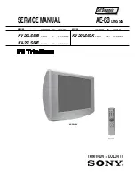
SERVICE MANUAL

AE-6B


CHASSIS

MODEL

COMMANDER

DEST

CHASSIS NO.

KV-29LS60B

RM-932

FR

SCC-Q83A-A

MODEL

COMMANDER

DEST

CHASSIS NO.

KV-29LS60K

RM-932

OIRT

SCC-Q82B-A

KV-29LS60

RM-932

KV-29LS60E

RM-932

ESP

SCC-Q81A-A

Содержание FD Trinitron KV-29LS60K

Страница 1: ...ERVICEMANUAL AE 6BCHASSIS MODEL COMMANDER DEST CHASSIS NO KV 29LS60B RM 932 FR SCC Q83A A MODEL COMMANDER DEST CHASSIS NO KV 29LS60K RM 932 OIRT SCC Q82B A KV 29LS60 RM 932 KV 29LS60E RM 932 ESP SCC Q81A A ...

Страница 2: ...ube 47 7 ELECTRICAL PARTS LIST 48 CAUTION SHORT CIRCUIT THE ANODE OF THE PICTURE TUBE AND THE ANODE CAP TO THE METAL CHASSIS CRT SHIELD OR THE CARBON PAINTED ON THE CRT AFTER REMOVAL OF THE ANODE CAP WARNING AN ISOLATION TRANSFORMER SHOULD BE USED DURING ANY SERVICE WORK TO AVOID POSSIBLE SHOCK HAZARD DUE TO LIVE CHASSIS THE CHASSIS OF THIS RECEIVER IS DIRECTLY CONNECTED TO THE POWER LINE SAFETY R...

Страница 3: ... u E n i p 1 2 2 s l a n g i s o e d i V d n a o i d u A r o f s t u p n I B G R r o f s t u p n I s l a n g i s o i d u A d n a o e d i V V T f o s t u p t u O e l b a t c e l e s s n o i s n e m i D m m 3 5 5 x 2 9 5 x 1 7 7 x o r p p A t h g i e W g k 9 4 x o r p p A s k c a J o n o h P o i d u A r o f e l b a i r a v s r o t c e n n o C t u p t u O s l a n g i S s e i r o s s e c c A d e i l p...

Страница 4: ...tput A left Standard level 0 5V rms Output impedence Less than 1kohm 4 Ground audio 5 Ground blue 6 Audio input A left Standard level 0 5V rms Output impedence More than 10kohm 7 Blue input 0 7 3dB 75 ohms positive 8 Function select AV control High state 9 5 12V Part mode Low state 0 2V TV mode Input impedence More than 10K ohms Input capacitance Less than 2nF 9 Ground green 10 Open 11 Green Green...

Страница 5: ...turn to establish if a device is faulty If a device is found to be faulty the relevant device number will be displayed through the LED Series of flashes which must be counted See table 1 non fatal errors are reported using this method Each time the software detects an error it is stored within the NVM See Table 2 Table 1 How to enter intoTable 2 1 Turn on the main power switch of the TV set 2 Prog...

Страница 6: ...essary press or to select Not necessary and press OK b If it is necessary press or to select Adjust now then press OK and correct any slant of the picture between 5 and 5 by pressing or Finally press OK to store 8 First Time Operation Your TV is now ready for use 5 The Auto Tuning menu appears on the screen Press the OK button to select Yes 6 The TV starts to automatically search and store all ava...

Страница 7: ...u System SOUND ADJUSTMENT The Sound Adjustment menu allows you to alter the sound adjustments To do this after selecting the item you want to alter press then press repeatedly or to adjust it and finally press OK to store the new adjustment Level 1 Level 2 Level 3 Function Effect Natural enhances clarity detail and presence of sound by using BBE High Definition Sound system Dynamic BBE High Defini...

Страница 8: ...ion press and then proceed in the same way as in step 7 b of the section Switching On the TV and Automatically Tuning PROGRAMME LABELS The Programme Labels option in the Set Up menu allows you to name a channel using up to five characters letters or numbers To do this 1 After selecting the option press then press or to select the programme number with the channel you wish to name 2 Press With the ...

Страница 9: ...to operate basic functions of this Sony TV Sony DVD and most of Sony VCR when batteries are initially installed To control other VCR and DVD major brands and some Sony VCR models please complete the following steps Before you start look up the 3 digit code for your brand of DVD or VCR from the list below On those brands that have more than one code enter the first code number Sony will endeavour t...

Страница 10: ...en viewing teletext Picture slanted Noisy picture when viewing a TV channel No unscrambling or unstable picture whilst viewing a scrambling channel with a decoder connected through the Scart connector 3 q 3 Remote control does not function The standby indicator on the TV flashes Solution Check the aerial connection Plug the TV in and press the button on the front of the TV If the standby indicator...

Страница 11: ...e chassis away from the beznet Ensure that the interconnecting leads are released from their purse locks to prevent damage being caused 2 2 Speaker Connector Disconnection When refitting the chassis ensure that the main bracket is located in the beznet guide slots before sliding the chassis forwards Refit the interconnecting leads in their respective purse locks Before completely removing the rear...

Страница 12: ...underside of the boards follow the instructions on page 15 Removal and Replacement of the main bracket bottom plates Clips 2 6 Side Control Module Removal 2 7 H2 Board Removal Remove the two screws fixing the user control module to the side of the set The control module can then be removed by sliding it towards the rear of the set allowing access to the H2 Board Screws To remove the H2 Board relea...

Страница 13: ...ble as indicated above The Extender board and extension cable are available as a service part by ordering the part number as indicated 2 8 M Board Removal To remove the M Board gently release the two clips with a screwdriver and remove the board from its socket vertically 2 9 Service Connector for M Board To A Board From M Board Extender Board Assembly A 1642 293 A ...

Страница 14: ...moval of the Anode Cap 2 10 Picture Tube Removal WARNING BEFORE REMOVING THE ANODE CAP High voltage remains in the CRT even after the power is disconnected To avoid electric shock discharge CRT before attempting to remove the anode cap Short between anode and CRT coated earth ground strap Coated Earth Ground Strap 1 Discharge the anode of the CRT and remove the anode cap 2 Unplug all interconnecti...

Страница 15: ...d by the arrows Note There are 3 plates fitted to the main bracket and secured by3 gates Only remove the necessary plate to gain access to the printed wiring board 2 REFITTING THE PLATES Because the plates differ in size it is important that the correct plates are refitted in their original location Please note that the plates need to be rotated 180 degrees from their cut position to allow the tab...

Страница 16: ...4 Digital multimeter Fig 3 1 2 Landing Note Before carrying out the following adjustments adjust the magnets as indicated below See Fig 3 4 1 Input a crosshatch signal from the signal generator 2 Rough adjust the focus and horizontal convergence 3 Switch from the crosshatch pattern to an all red pattern 4 Move the deflection yoke backwards and adjust with the purity magnet so that the red is at th...

Страница 17: ... the direction indicated below Note Do not adjust the H STAT by rotating the V STAT magnets as this can affect the focus setting B G R B G R Fig 3 5 Purity magnets Align pips on each magnet Fig 3 4 Align both Purity magnets to the vertical position Purity control corrects this area Disk magnets or rotatable disk magnets correct these areas a d Deflection yoke positioning corrects these areas a c d...

Страница 18: ...e section of the service menu HTIL correction can be performed by adding a THL correction assembly to the Deflection yoke C D C D C D C D R G B C D C D R G B R G B R G B VMC correction A VMC correction B THL Correction assy HAMP Adjustment HTIL Adjustment YCH Adjustment HMC correction A HMC correction B A B A B R G B R G B A B A B R G B R G B TLV Adjustment H TRAP Adjustment The H TRAP should not ...

Страница 19: ...f permalloy magnets 1 Input an all white signal from the pattern generator 2 Program the Remote Commander for operation in Service Mode See Page 20 3 Enter into the Service Mode by pressing VIDEO button twice and MENU on the Service Commander 4 Select Service from the on screen menu display and press Right Arrow 5 The Service menu will appear on the screen See Page 21 6 Set the Contrast to MAX 7 S...

Страница 20: ...u switch the TV set OFF and then ON y r t e m o e G e c i v r e S e t a r n a c S C A D v n o C n y D P i P d n u o S t s u j d a F I u n e M r o r r E 1 0 0 2 n u J 4 1 0 v B 6 E A h F F h F F a t a d y r o t c a F G 1 1 4 3 P S M e c i v e D P S M Y R T E M O E G H T L B A E D O M L B A L B A P E Z I S V N O I T I S O P V P M O C V N I L V N O I T C E R R O C S E Z I S H P M A N I P N I P R E N ...

Страница 21: ...E 5 1 E 6 1 E E M I T G N I K R O W S R U O H S E T U N I M P C O P V O C N Y S V R K I C I I M V N T O R P H R E N U T P D N U O S E T A R N A C S C A D D N E K C A B N O C N Y D P I P 5 5 2 0 5 5 2 0 5 5 2 0 5 5 2 0 5 5 2 0 5 5 2 0 5 5 2 0 5 5 2 0 5 5 2 0 5 5 2 0 5 5 2 0 5 5 2 0 5 5 2 0 5 5 2 0 5 5 2 0 0 0 0 0 0 0 0 0 0 0 0 0 0 0 0 4 1 7 T S U J D A F I e t u m o t u A n i a G o i d u A g n i t ...

Страница 22: ...t u h S o t u A 6 3 t s e t N O F F O M V n o i t a l u d o M y t i c o l e V 1 4 M V N e s i l a i t i n i e R 3 4 d n u o s A l a u D t c e l e S 4 4 d n u o s B l a u D t c e l e S 5 4 d n u o s o n o M t c e l e S 6 4 d n u o s o e r e t S t c e l e S 8 4 n i g r i v n o n s a M V N t e S 9 4 n i g r i v s a M V N t e S 3 5 e l b a s i D e l b a n E n o i t a l u d o m r e v O M F 5 5 S P L A ...

Страница 23: ... KEY 47 48 1 6 4 9 LEFT Y CVBS FRONT RIGHT CN2000 FR IN L FR IN R LED 2 1 SIRCS CN0103 BACKEND DEFLECTION RGB PROCESSOR IC7002 33 YSYM 2 34 B2 IN G2 IN 36 R2 IN 35 30 26 R OUT B OUT FS 100 B TXT G TXT R TXT 52 Y1 IN U IN 100 28 G OUT 53 CB1 IN 54 CR1 IN HS IN 60 VS IN 59 V IN 100 H SYNC V SYNC PIP Y 56 Y2 IN PIP CB 57 CB2 IN PIP CR 58 CR2 IN 63 EXTRA PARA 64 DF PARA 1 EW OUT 17 HD OUT 18 HP IN 20 ...

Страница 24: ...B13 FS 100 A13 AUDIO MUTE B12 R TEXT A12 RESET AUDIO B11 G TEXT B10 B TEXT A9 DGC RY B8 MAIN RY A8 COINCIDENCE B7 OCP A7 GROUP DELAY B6 OVP B5 MODE 3 A5 AGC B4 SIRCS A4 LED B3 SDA A3 SCL PART OF OVERVOLTAGE PROTECTION Q5816 COINCIDENCE DETECTOR Q1005 VIDEO RF CVBS TXT V SYNC H SYNC 12 C ADAPTOR 5V 3 3V Q3500 12 C ADAPTOR 5V 3 3V Q3501 OVP 3 3V 2 1 CN6200 TO M BOARD CN0001 CN0102 SERVICE CONNECTOR ...

Страница 25: ...805 H LIN Q8806 DF DRIVE Q8851 Q8203 8 8 HD1 TO A BOARD CN5002 D DEFLECTION D8819 D8808 15V D8807 15V D8805 5 1 BLOCK DIAGRAMS 3 DGC 10 6V AU CN6001 RECT D6102 AC IN AC IN TO F4 BOARD CN6992 G POWER SUPPLY 1 5 CN6002 CHECK CHECK 1 2 1 2 3 CN6003 CN6004 PFC PFC 1 3 CN6008 MAIN RY DGC RY TO A BOARD CN6200 1 2 DGC DGC 3 1 T6003 4 2 3 1 T6101 4 2 9 7 8 RELAY SWITCH Q6103 11 12 13 14 15 16 17 18 1 2 3 ...

Страница 26: ...umbers specified in the parts list Note CVM Board A Board S1 Board VM C H D1 A J A2 N D A1 D2 C A 5 1 BLOCK DIAGRAMS 4 A 0 A 1 A 2 A 3 A 4 A 5 A 6 A 7 A 8 A 9 A 10 A 11 A 12 A 13 A 14 A 15 A 16 A 17 CN001 MICRO CONTROLLER IC0002 M MICRO PROCESSOR NVM MEMORY IC0001 5 A3 SCL 7 6 B3 SDA 28 A4 LED LED 76 B4 SIRCS SIRCS AGC AGC 22 A5 MODE 3 AGC 29 B6 OVP 80 A7 GROUP DELAY 24 B7 OCP OVP OCP 59 A8 COINCI...

Страница 27: ... 27 A Schematic Video Audio Processors Audio Output Vertical Deflection page 1 2 ...

Страница 28: ...ardWaveforms A Board DifferenceTable f e R B 0 6 S L 9 2 E 0 6 S L 9 2 K 0 6 S L 9 2 1 1 0 1 C F P 0 2 1 2 1 0 1 C F P 6 5 6 1 0 1 C F P 0 1 7 1 0 1 C F P 8 6 4 0 0 1 L H U 8 1 2 0 0 1 Q 1 T S R 1 0 6 D S M 3 0 0 1 Q A K E 4 1 1 C T D 6 4 1 T 1 1 0 1 R 0 3 3 2 1 0 1 R 0 3 3 4 1 0 1 R 0 T R O H S 0 T R O H S 5 1 0 1 R 0 7 4 6 1 0 1 R 0 0 1 8 1 0 1 R K 2 2 0 2 0 1 R 0 T R O H S 0 0 0 1 U T 1 1 4 F E...

Страница 29: ...A B C D E F G H I J K L M N 1 2 3 4 5 6 7 8 9 10 11 29 A PrintedWiring Board Conductor side A ...

Страница 30: ...A B C D E F G H I J K L M N 1 2 3 4 5 6 7 8 9 10 11 30 A PrintedWiring Board Conductor side B ...

Страница 31: ...I 9 I 3 0 0 2 Q 9 D 1 0 1 5 Q 5 M 1 0 4 5 Q 4 K 7 1 0 7 Q 6 I 5 1 0 2 D 9 D 5 1 0 3 D 4 C 3 0 3 5 D 4 N C I 1 0 2 6 C I 8 I 4 0 0 2 Q 7 E 0 0 2 5 Q 4 M 2 0 4 5 Q 5 J 8 1 0 7 Q 5 I 6 1 0 2 D 8 E 7 1 0 3 D 4 B 4 0 3 5 D 4 M 0 0 0 2 C I 8 C 2 0 2 6 C I 6 F 5 0 0 2 Q 7 E 1 0 2 5 Q 3 N 3 0 4 5 Q 4 J 9 1 0 7 Q 5 I 8 1 0 2 D 2 B 8 1 0 3 D 3 B 5 0 3 5 D 6 L 1 0 0 2 C I 9 D 3 0 2 6 C I 6 E 1 0 5 2 Q 8 G 2 ...

Страница 32: ...geTable A Board IC Voltage Table e l b a T e g a t l o V C I o N f e R o N n i P V e g a t l o V o N f e R o N n i P V e g a t l o V o N f e R o N n i P V e g a t l o V o N f e R o N n i P V e g a t l o V o N f e R o N n i P V e g a t l o V 0 0 1 3 C I 1 3 1 3 0 1 5 C I 6 8 1 1 0 2 5 C I 5 3 9 0 0 4 5 C I 6 7 3 1 2 0 0 7 C I 2 3 9 8 2 7 1 7 2 6 5 0 7 4 1 3 3 0 3 6 2 8 0 7 1 2 1 2 0 0 7 C I 1 6 3 4...

Страница 33: ...A B C D E F G H I J K L M N 1 2 3 4 5 6 7 8 9 10 11 33 VM Board Schematic Diagram Velocity Modulation H2 Board Schematic Diagram Front AV Headphone F2 Board Schematic Diagram Power Switch Fuse ...

Страница 34: ... 3 0 6 D 2 D 7 0 0 6 Q 3 H 9 0 0 6 D 4 E 3 3 0 6 D 2 E 8 0 0 6 Q 4 D 0 1 0 6 D 4 E 4 3 0 6 D 2 E 9 0 0 6 Q 4 E 1 1 0 6 D 3 E C I 0 1 0 6 Q 2 B 2 1 0 6 D 3 E 1 0 0 6 C I 5 G 4 1 0 6 Q 2 J 3 1 0 6 D 3 A 1 0 1 6 Q 1 L Note Portions of the circuit contained within the marked areas as shown have high voltages present Use care to prevent electric shock during inspection or repair An Isolation Transforme...

Страница 35: ... 35 G Board Schematic Diagram Power Supply ...

Страница 36: ... 36 D Board Schematic Diagram Deflection ...

Страница 37: ... 0 4 0 9 8 8 1 1 8 Q 0 0 0 5 6 3 1 8 Q 5 2 8 1 0 8 1 8 8 Q 0 0 0 5 4 0 1 8 Q 0 4 0 1 3 9 1 1 8 Q 7 0 4 1 0 7 3 1 8 Q 8 1 5 2 9 8 2 2 8 8 Q 5 5 9 4 0 5 0 1 8 Q 0 4 0 2 3 0 2 1 8 Q 7 0 3 2 0 1 0 2 8 Q 0 6 0 9 3 3 2 8 8 Q 9 8 5 8 0 6 0 1 8 Q 0 3 0 3 4 2 2 1 8 Q 5 0 4 1 0 2 0 2 8 Q 0 8 0 4 3 5 0 8 8 Q 0 5 2 3 3 7 0 1 8 Q 0 3 0 2 4 3 2 1 8 Q 5 0 4 1 0 3 0 2 8 Q 4 1 9 0 0 6 0 8 8 Q 0 2 1 5 3 1 8 0 1 8 Q...

Страница 38: ...A B C D E F G H I J K L M N 1 2 3 4 5 6 7 8 9 10 11 38 C Board Schematic R G B Out ...

Страница 39: ...H TP4 TP5 TP6 TP7 C BoardWaveforms f e R e b c 0 5 3 7 Q 2 1 8 9 1 1 0 2 5 3 7 Q 0 0 8 3 3 5 3 7 Q 0 0 8 3 4 5 3 7 Q 8 9 1 1 2 1 0 5 5 3 7 Q 0 0 8 3 C Board Semiconductor VoltageTable e l b a T e g a t l o V C I o N f e R o N n i P V e g a t l o V 0 0 3 7 C I 1 9 3 3 8 3 5 5 7 6 0 0 2 7 0 4 1 8 3 5 1 9 0 4 1 5 2 3 7 C I 1 9 3 3 8 3 5 7 7 6 0 0 2 7 0 4 1 8 3 5 1 9 0 4 1 0 5 3 7 C I 1 9 3 3 8 3 5 5 ...

Страница 40: ... 40 M Board Schematic Diagram Micro Processor ...

Страница 41: ...A LM318P LM358N LM393DT LM393N M24C16 MN6T A LM78L05ACZ MSP3411G QA B10 8 7 6 5 1 3 4 2 IN GND OUT 68 61 60 1 52 44 43 35 27 26 18 10 9 TOP VIEW NJM3404AD W UPC4558G2 TOP VIEW 1 4 8 5 PQ30RV11 1 1 V IN 2 V OUT 3 GND 4 ON OFF CONTROL 2 3 4 PST573IMT 1 3 2 Vcc Out Gnd 1 2 3 SAA5665HL M1D 0358 SDA9488X B23GEG 1 100 25 26 50 51 75 76 1 14 15 28 SBX3081 51 30 STV9379 7 1 ...

Страница 42: ... SPA07N60C2 2SA2005 2SC5511 DTA144EK DTC144TKA T146 2SA1162 G DTA144ESA 2SA933AS QT 2SC2785 HFE B C E B C E C B E L7809CV LSY STP5NB40FP STP5NB40 030Y 2SC5698 CA 2S5696 SONY CA MSB709 RT1 MSD601 RST1 M1MA152WA T1 UN2111 UN213 2SK2036 TE85L E RB705D SE135N LF4 2 1 3 1 3 2 1 2 3 1 V OUT SENSE 2 COLLECTOR 3 GND 2SA1837 LBS2S0N E C B 2SB734 34 1 2 3 ...

Страница 43: ...DE ANODE TLHK5190 FBIU4D7MA B RBV 406B S1VB40 CATHODE ANODE MTZJ T 77 22 RD15ES B2 RD39ES B2 RD5 6ESB2 1SS119 25 1SS133T 77 GS1B460 45 D2S4MTA1 BYV98 200 RAS 15 12 CATHODE ANODE D1NL20U EGP20G EL1Z GP08D UF4005PKG23 CATHODE ANODE BAS316 115 MMDL914T1 UDZSTE 176 2B CATHODE ANODE ...

Страница 44: ...MP 30K 30K 60K 5 5 IC BLOCK DIAGRAMS 4 3 2 6 7 1 5 Vsense Remote DVLD Internal OFF Latch Centre Osc SS F B Timer TSD OCP Control Logic Level Shift Sel 34v ref 5v 15v 8v Driver Reg 10v 18 8 14 16 15 10 12 11 9 A BOARD IC6202 IC6207 IC6205 BA033T BA12T G BOARD IC6001 MCZ3001D A BOARD IC2500 TDA7497 ...

Страница 45: ...face 25 23 65 68 1 3 4 5 7 6 48 50 51 47 30 34 31 28 33 37 36 DEMODULATOR A BOARD IC2000 MSP3411G 1 5 4 3 8 7 2 6 9 G BOARD IC6003 SE135N LF4 FLYBACK GENERATOR THERMAL PROTECTION 2 6 3 5 4 7 1 POWER AMPLIFIER A BOARD IC5400 STV9379 1 2 3 7 5 6 A BOARD IC5301 IC5302 LM393TD A BOARD IC5300 LM358N 1 2 3 4 6 5 7 8 ...

Страница 46: ...D LOCK SC 5 1 765 286 11 CORD POWER 6 1 424 855 11 COIL CHOKE 7 4 206 106 01 BRACKET MAIN 8 A 1637 024 A G BOARD COMPLETE 9 8 598 535 11 FRONTEND BTF EF411 KV 29LS60B 8 598 533 01 FRONTEND BTF EC411 KV 29LS60E 29LS60K 10 A 1634 062 A M BOARD COMPLETE 11 A 1632 954 A A BOARD COMPLETE KV 29LS60B A 1632 955 A A BOARD COMPLETE KV 29LS60E 29LS60K 12 1 453 340 31 TRANSFORMER ASSY FLYBACK NX 4522 Z2B4 13...

Страница 47: ...TATION RT200 61 A 1644 119 A VM BOARD COMPLETE 62 A 1638 158 A C BOARD COMPLETE 63 4 369 318 21 SPRING TENSION 64 1 424 887 11 COIL DEGAUSSING 65 4 203 390 11 CUSHION DGC 66 4 204 768 01 HOLDER DGC 29 67 8 453 011 41 NECK ASSY NA299 C 68 1 251 946 11 CAP ASSY HIGH VOLTAGE 69 3 704 495 01 SPACER DY 70 4 046 765 12 SCREW TAPPING 7 CROWN WASHER 71 4 308 870 00 CLIP LEAD WIRE 72 1 452 094 00 MAGNET RO...

Страница 48: ...F2 BOARD COMPLETE Parts List 49 A BOARD COMMON Parts List Parts common to all models listed in this manual 49 A BOARD VARIANT Parts List Parts that belong only to the model specified Model KV 29LS60B 57 KV 29LS60E 58 KV 29LS60K 58 M BOARD COMPLETE Parts List 58 G BOARD COMPLETE Parts List 59 C BOARD COMPLETE Parts List 61 D BOARD COMPLETE Parts List 62 H2 BOARD COMPLETE Parts List 66 VM BOARD COMP...

Страница 49: ...CHIP 0 0047UF 10 00 50V C2001 1 162 968 11 CERAMIC CHIP 0 0047UF 10 00 50V C2006 1 162 962 11 CERAMIC CHIP 470PF 10 00 50V C2007 1 163 021 91 CERAMIC CHIP 0 01UF 10 00 50V C2008 1 162 964 11 CERAMIC CHIP 0 001UF 10 00 50V C2009 1 163 021 91 CERAMIC CHIP 0 01UF 10 00 50V C2010 1 162 964 11 CERAMIC CHIP 0 001UF 10 00 50V C2011 1 162 962 11 CERAMIC CHIP 470PF 10 00 50V C2013 1 162 962 11 CERAMIC CHIP...

Страница 50: ...964 11 ELECT 10UF 20 00 50V C3211 1 126 964 11 ELECT 10UF 20 00 50V C3213 1 164 222 91 CERAMIC CHIP 0 22UF 25V C3214 1 164 222 91 CERAMIC CHIP 0 22UF 25V C3215 1 164 222 91 CERAMIC CHIP 0 22UF 25V C3216 1 164 222 91 CERAMIC CHIP 0 22UF 25V C3217 1 164 222 91 CERAMIC CHIP 0 22UF 25V C3218 1 164 222 91 CERAMIC CHIP 0 22UF 25V C3219 1 164 222 91 CERAMIC CHIP 0 22UF 25V C3220 1 164 222 91 CERAMIC CHIP...

Страница 51: ...ELECT 100UF 20 00 50V C5410 1 163 021 91 CERAMIC CHIP 0 01UF 10 00 50V C5411 1 137 401 11 MYLAR 0 22UF 10 00 100V B1 A C5412 1 106 220 00 MYLAR 0 1UF 10 00 100V C5413 1 130 785 11 MYLAR 0 47UF 10 00 100V C5801 1 126 963 11 ELECT 4 7UF 20 00 50V C5850 1 126 963 11 ELECT 4 7UF 20 00 50V C5851 1 107 826 11 CERAMIC CHIP 0 1UF 10 00 16V C5853 1 162 970 11 CERAMIC CHIP 0 01UF 10 00 25V C5854 1 107 826 1...

Страница 52: ...ODE M1MA152WK T1 A F4 A C7030 1 164 004 11 CERAMIC CHIP 0 1UF 10 00 25V C7031 1 164 004 11 CERAMIC CHIP 0 1UF 10 00 25V C7032 1 164 004 11 CERAMIC CHIP 0 1UF 10 00 25V C7038 1 107 823 11 CERAMIC CHIP 0 47UF 10 00 16V C7039 1 162 966 11 CERAMIC CHIP 0 0022UF 10 00 50V C7050 1 162 927 11 CERAMIC CHIP 100PF 5 00 50V C7051 1 164 004 11 CERAMIC CHIP 0 1UF 10 00 25V C7052 1 164 004 11 CERAMIC CHIP 0 1UF...

Страница 53: ...8 2UH L2500 1 535 143 61 LEAD JUMPER 5 0MM L2501 1 535 143 61 LEAD JUMPER 5 0MM L3000 1 216 295 91 SHORT 0 L3004 1 216 295 91 SHORT 0 L3005 1 216 295 91 SHORT 0 L3006 1 216 295 91 SHORT 0 L3007 1 216 295 91 SHORT 0 L3008 1 216 295 91 SHORT 0 L3009 1 216 295 91 SHORT 0 L3010 1 216 295 91 SHORT 0 L3011 1 216 295 91 SHORT 0 L3012 1 216 295 91 SHORT 0 L3200 1 412 006 31 INDUCTOR 10UH L3202 1 412 006 3...

Страница 54: ...7 1 216 049 11 RES CHIP 1K 5 1 10W R2078 1 216 025 11 RES CHIP 100 5 1 10W R2079 1 216 049 11 RES CHIP 1K 5 1 10W R2080 1 216 831 11 RES CHIP 6 8K 5 1 16W A Q3501 8 729 028 28 TRANSISTOR 2SK2036 TE85L Q5101 8 729 010 29 TRANSISTOR MSD601 RST1 Q5200 8 729 010 29 TRANSISTOR MSD601 RST1 Q5201 8 729 010 29 TRANSISTOR MSD601 RST1 Q5202 8 729 045 04 TRANSISTOR 2SC5511 Q5203 8 729 044 59 TRANSISTOR 2SA18...

Страница 55: ...1 RES CHIP 1K 5 1 16W R5140 1 216 821 11 RES CHIP 1K 5 1 16W R5141 1 216 833 11 RES CHIP 10K 5 1 16W R5143 1 216 833 11 RES CHIP 10K 5 1 16W A R2081 1 216 833 11 RES CHIP 10K 5 1 16W R2082 1 216 031 91 RES CHIP 180 5 1 10W R2083 1 216 817 11 RES CHIP 470 5 1 16W R2090 1 216 829 11 RES CHIP 4 7K 5 1 16W R2091 1 216 829 11 RES CHIP 4 7K 5 1 16W R2092 1 216 039 00 RES CHIP 390 5 1 10W R2093 1 216 039...

Страница 56: ...06 11 METAL CHIP 10K 0 5 1 10W R5305 1 208 852 11 METAL CHIP 820K 0 5 1 10W R5306 1 208 803 11 METAL CHIP 7 5K 0 5 1 10W R5307 1 216 041 00 RES CHIP 470 5 1 10W R5308 1 216 295 91 SHORT 0 R5309 1 208 824 91 RES CHIP 56K 0 5 1 10W R5310 1 208 830 11 METAL CHIP 100K 0 5 1 10W R5311 1 216 045 00 RES CHIP 680 5 1 10W R5312 1 208 832 11 METAL CHIP 120K 0 5 1 10W R5314 1 208 840 11 METAL CHIP 270K 0 5 1...

Страница 57: ...100 5 1 10W R7052 1 216 025 11 RES CHIP 100 5 1 10W R7053 1 216 049 11 RES CHIP 1K 5 1 10W R7054 1 216 847 11 RES CHIP 150K 5 1 16W R7056 1 216 831 11 RES CHIP 6 8K 5 1 16W R7057 1 216 842 11 RES CHIP 56K 5 1 16W R7058 1 216 049 11 RES CHIP 1K 5 1 10W R7065 1 216 821 11 RES CHIP 1K 5 1 16W R7066 1 216 809 11 RES CHIP 100 5 1 16W R7068 1 216 681 91 METAL CHIP 18K 0 5 1 10W R7070 1 216 817 11 RES CH...

Страница 58: ...017 1 216 295 91 SHORT 0 FB0018 1 216 295 91 SHORT 0 FB0019 1 216 295 91 SHORT 0 FB0020 1 216 295 91 SHORT 0 IC IC0001 8 759 699 33 IC M24C16 MN6T A IC0002 6 700 502 01 IC SAA5665HL M1D 0358 IC0003 8 759 672 39 IC PST573IMT IC0004 8 759 665 11 IC LM393DT IC0005 6 700 132 01 IC K6T2008V2A YF70T00 TRANSISTOR Q0002 8 729 424 08 TRANSISTOR UN2111 Q0003 8 729 424 08 TRANSISTOR UN2111 M A RESISTOR R1011...

Страница 59: ...0053 1 216 809 11 RES CHIP 100 5 1 16W R0054 1 216 809 11 RES CHIP 100 5 1 16W R0055 1 216 809 11 RES CHIP 100 5 1 16W R0056 1 216 833 11 RES CHIP 10K 5 1 16W R0057 1 216 809 11 RES CHIP 100 5 1 16W G H5 M R0058 1 216 823 91 RES CHIP 1 5K 5 1 16W R0059 1 216 841 11 RES CHIP 47K 5 1 16W R0060 1 216 833 11 RES CHIP 10K 5 1 16W R0061 1 216 833 11 RES CHIP 10K 5 1 16W R0062 1 216 833 11 RES CHIP 10K 5...

Страница 60: ...081 97 DIODE MMDL914T1 D6008 8 719 063 70 DIODE D1NL20U D6009 8 719 110 41 DIODE RD15ES B2 D6010 8 719 085 24 DIODE FBIU4D7M1 B D6016 8 719 309 99 DIODE RBV 406B D6031 8 719 080 59 DIODE EK19 V0 D6032 8 719 080 59 DIODE EK19 V0 D6033 8 719 022 99 DIODE D2S4MTA1 D6034 8 719 022 99 DIODE D2S4MTA1 D6101 8 719 081 97 DIODE MMDL914T1 D6102 8 719 511 40 DIODE S1VB20 S G D6103 8 719 081 97 DIODE MMDL914T...

Страница 61: ...29 11 RES CHIP 4 7K 5 1 16W R6110 1 216 821 11 RES CHIP 1K 5 1 16W RELAY RY6001 1 755 395 11 RELAY AC POWER RY6002 1 755 389 11 RELAY AC POWER TRANSFORMER T6002 1 437 443 11 TRANSFORMER PIT T6003 1 424 896 11 TRANSFORMER LINE FILTER T6101 1 437 483 11 TRANSFORMER STANDBY THERMISTOR TH6002 1 803 541 11 THERMISTOR A 1638 158 A C Board Complete 4 382 854 01 SCREW M3X8 P SW CAPACITOR C7303 1 162 909 9...

Страница 62: ... 20 1 2W R7388 1 535 143 51 LEAD JUMPER 20 0MM R7390 1 249 417 11 CARBON 1K 5 1 4W R7391 1 216 824 11 RES CHIP 1 8K 5 1 16W R7393 1 216 823 11 RES CHIP 1 5K 5 1 16W R7394 1 249 417 11 CARBON 1K 5 1 4W R7395 1 216 824 11 RES CHIP 1 8K 5 1 16W R7397 1 216 823 11 RES CHIP 1 5K 5 1 16W R7398 1 249 417 11 CARBON 1K 5 1 4W R7399 1 216 824 11 RES CHIP 1 8K 5 1 16W VARIABLE RESISTOR RV7375 1 241 656 11 RE...

Страница 63: ... 205 11 MYLAR 0 022UF 10 00 400V C8856 1 102 030 00 CERAMIC 330PF 10 00 500V C8860 1 162 964 11 CERAMIC CHIP 0 001UF 10 00 50V C8861 1 162 927 11 CERAMIC CHIP 100PF 5 00 50V C8869 1 162 964 11 CERAMIC CHIP 0 001UF 10 00 50V CONNECTOR CN8600 1 564 509 11 PLUG CONNECTOR 6P CN8601 1 564 506 11 PLUG CONNECTOR 3P CN8611 1 785 270 12 PIN DY CONNECTOR PC BOARD CN8612 1 564 511 51 PLUG CONNECTOR 8P CN8614...

Страница 64: ...13 11 RES CHIP 220 5 1 16W R8102 1 216 825 11 RES CHIP 2 2K 5 1 16W R8103 1 216 825 11 RES CHIP 2 2K 5 1 16W R8104 1 216 825 11 RES CHIP 2 2K 5 1 16W R8105 1 216 821 11 RES CHIP 1K 5 1 16W R8106 1 216 825 11 RES CHIP 2 2K 5 1 16W R8107 1 208 792 91 RES CHIP 2 7K 5 1 10W R8108 1 208 792 91 RES CHIP 2 7K 5 1 10W R8109 1 208 814 91 METAL CHIP 22K 0 5 1 10W R8110 1 208 814 91 METAL CHIP 22K 0 5 1 10W ...

Страница 65: ...15 485 00 METAL 470K 1 1 4W R8898 1 215 493 00 METAL 1M 1 1 4W R8899 1 215 493 00 METAL 1M 1 1 4W R8160 1 216 295 91 SHORT 0 R8161 1 208 804 11 METAL CHIP 8 2K 0 5 1 10W R8162 1 216 821 11 RES CHIP 1K 5 1 16W R8163 1 216 833 11 RES CHIP 10K 5 1 16W R8164 1 208 814 91 METAL CHIP 22K 0 5 1 10W R8165 1 208 830 11 METAL CHIP 100K 0 5 1 10W R8168 1 216 829 11 RES CHIP 4 7K 5 1 16W R8169 1 208 830 11 ME...

Страница 66: ...TOR 10UH L7403 1 414 934 21 INDUCTOR 10UH TRANSISTOR Q7400 8 729 010 29 TRANSISTOR MSD601 RST1 Q7401 8 729 010 29 TRANSISTOR MSD601 RST1 Q7402 8 729 010 29 TRANSISTOR MSD601 RST1 H2 VM TRANSFORMER T8800 1 453 340 31 TRANSFORMER ASSY FLYBACK NX 4522 Z2B4 T8801 1 437 430 11 TRANSFORMER FERRITE HDT T8802 1 437 430 11 TRANSFORMER FERRITE HDT T8852 1 433 487 11 TRANSFORMER FERRITE DFT A 1647 043 A H2 B...

Страница 67: ...7 1 216 025 11 RES CHIP 100 5 1 10W R7428 1 216 033 00 RES CHIP 220 5 1 10W R7429 1 216 033 00 RES CHIP 220 5 1 10W R7432 1 216 065 91 RES CHIP 4 7K 5 1 10W R7433 1 247 787 91 RES CHIP 15 5 1 4W R7434 1 249 395 11 CARBON 15 5 1 4W R7435 1 216 033 91 RES CHIP 220 5 1 10W R7436 1 216 049 91 RES CHIP 1K 5 1 10W VM MISCELLANEOUS 1 571 433 21 SWITCH PUSH AC POWER 1 765 286 11 CORD POWER 1 424 855 11 CO...

Страница 68: ......

Страница 69: ...e modules Please contact your local Sony Service organisation for the latest information Read restore and compare NVM contents via the I2C bus Acknowledge check of all I2C devices in the TV set Read Error Codes emulation of the Error Reader tool Remote Commander emulation User programmable Functional Check through Infrared Fast and documented Test Mode setting of all Sony TV chassis Partnumbers TR...

Отзывы: