


8
For details on the transmitter’s remaining battery
indicator settings and battery replacement, refer to the
transmitter’s operating instructions.
j
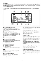
Transmission power indicator
Indicates the current transmission power set on the
transmitter. This setting can be changed in the
TRANSMITTER menu.
k
ALERT (alert) indicator
Lights up red when error is detected.
For the specific causes of alerts and remedies, see “When
the ALERT Indicator Lights” (page 35).
l
Reception channel information
Shows the information on receiving signal and the
transmitter name.
First row:
Group and channel
Middle row:
Frequency of the channel
Last row:
Transmitter name and sleep state
m
RF (radio reception) indicator
Lights up to indicate the level of the signal input from the
ANTENNA IN connector as follows.
On in orange:
87 dBµ or more (0 dBµ = 1 µV
EMF
)
On in green:
25 dBµ to 87 dBµ (0 dBµ = 1 µV
EMF
)
On in red:
15 dBµ to 25 dBµ (0 dBµ = 1 µV
EMF
)
Off:
Less than 15 dBµ (0 dBµ = 1 µV
EMF
)
n
RF (radio reception) level meters
Indicates the level of the signal input from the
ANTENNA IN connector. The number of segments that
light up depends on the input level.
o
Antenna selection indicator
Indicates the antenna currently selected by the diversity
function.
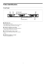
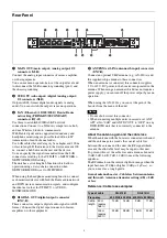
2
Controls
The control areas for channel 1 and channel 2 are
identical.
a
MONITOR (monitor output) button
Press to monitor the output of the selected receiver
channel via the headphones.
The UTILITY > AUDIO > MONITOR MODE setting
allows you to output only the selected receiver channel,
output a mix of multiple channels, or otherwise configure
the monitor output.
When MONITOR MODE is set to IP SOLO or IP MIX,
hold down the MONITOR button until it lights.
For details, see “Monitor mode setting (MONITOR
MODE)” (page 27).
b
Jog dial
Rotate to select an item or a parameter value in the menu.
Press to enter the selected item or parameter value.
c
RX (RECEIVER menu) button
Press to enter the RECEIVER menu. While in the
RECEIVER menu, this button lights up brightly.
d
REMOTE (RF REMOTE menu) button
Press to enter the RF REMOTE menu. While in the RF
REMOTE menu, this button lights up brightly.
e
TX (TRANSMITTER menu) button
Press to enter the TRANSMITTER menu. While in the
TRANSMITTER menu, this button lights up brightly.
f
ESC (escape) button
Press to go back to the previous menu display.
Transmission power indicator
H
M
L
DWT-B03R
25 mW
10 mW
2 mW
Other transmitters
50 mW
10 mW
1 mW
Note
1
2
3
4
5
6


