


28
DWX device networks to enable communication
between devices, and the monitor mode setting must be
the same on each device.
• When MONITOR MODE is set to IP SOLO or IP MIX,
hold down the MONITOR button until it lights.
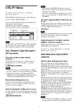
Sync signal setting
(SYNC SOURCE)
Selects the sync signal source for the receiver.
The receiver supports an external sync signal (word
clock) of 32 kHz to 96 kHz.
The synchronization status is indicated by “INT” or
“EXT” in the digital output sync indication on the top
display. When “EXT” is indicated and synchronization is
unlocked, the indication flashes.
INTERNAL:
The internal sync signal (48 kHz) is used.
EXTERNAL:
Synchronization with an external word
clock signal.
AUTO:
The external sync signal is used on a priority
basis. When there is no external sync signal input, the
internal sync signal is used automatically.
Display and adjustment of audio signal
delay times between channels
(DELAY
ADJUST)
During communications between the digital wireless
transmitter and digital wireless receiver, an audio signal
delay will occur as a result of audio signal processing on
both devices.
Display of audio signal delay times
The unit can display the total audio signal delay time of
the transmitter and the receiver for each channel using the
metadata sent from the transmitter.
Refer to this display when adjusting the delay time using
a device such as mixer or delay processor.
Display example
1CH D : 2.5ms , A : 1.5ms
2CH D : 2.5ms , A : 1.5ms
D: DIGITAL OUT
A: ANALOG OUT
Compensating delay times for receiver channels
1 and 2
The delay times for receiver channels 1 and 2 may be
different when the unit is used with two digital wireless
transmitters of differing models. By setting this
compensation function to ON in such cases, you can
automatically adjust the receiver channel with the shorter
audio signal delay time to match the channel with the
longer delay.
When adjusting the delay time manually using a device
such as mixer or delay processor, set this function to OFF.
AF peak level hold duration setting
(AF PEAK HOLD)
Set the peak level hold condition for the audio level meter
that appears on the top display and other situations.
2SEC:
Hold the audio level meter’s peak display for 2
seconds.
HOLD:
Hold the audio level meter’s peak display until it
is released.
Releasing the peak display
You can release the peak display by pressing the jog dial
while the top display is displayed. To release the peak
display while AF PEAK HOLD is set to HOLD, display
the top display for each channel and press the jog dial.
SUB OUT output setting
(SUB OUT SEL)
Selects the signal to output from the SUB OUT 1/2
connectors.
AES/EBU:
Output a digital audio signal in AES3 format.
ANALOG:
Output a balanced audio signal.
Items Related to Redundancy
(REDUNDANCY submenu)
Channel auto switching setting when
using multiple receivers
(AUTO FREQ CHANGE)
This function searches for channels on the host
DWR-R03D unit, and then automatically switches
channels assigned to other client DWR-R03D units with
poor signal reception to channels with good signal
reception.
For details, see “Switching to a Safe Frequency
Automatically” (page 17).
Audio output swap setting
(OUTPUT SWAP)
You can swap the audio outputs of tuner 1 and tuner 2 in
response to a specific action.
OFF:
Disable swapping of audio outputs.
ON:
Enable swapping of audio outputs.
• This function cannot be used when the AUTO FREQ
CHANGE function or CHANNEL COORDINATE
function is enabled.
• This function cannot be used when 4-ANTENNA is
selected using the DIVERSITY setting.
To swap audio outputs
When either the tuner 1 display or tuner 2 display is the
top screen, press and hold the jog dial of tuner 1 or tuner
2 for 1 seconds or longer.
When the audio outputs are swapped, the row showing
the transmitter name on the display is highlighted
(inverted), and “[OUT1]” and “[OUT2]” are swapped at
the end of the row.
The audio output swap is not maintained when the power
is turned off. To restart the operation when the power is
turned on, reconfigure the audio output swap as required.
Notes
Note


