9
Attachment and Connections
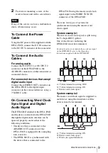
2
Fasten four mounting screws of the
receiver/tuner unit with a screwdriver.
If any of the screws are loose, malfunction
due to vibration may occur.
To Connect the Power
Cable
Using the DC power cable supplied with the
DWA-F01D, connect the DC IN connector
to the DC OUT connector of the camcorder.
To Connect the Audio
Cables
For analog audio
Connect the OUTPUT 1 or OUTPUT 2
connector on the DWA-F01D to the
AUDIO IN connectors on the camcorder or
connected device.
For connected devices that accept
digital audio input
Connect the AES/EBU OUT connector on
the DWA-F01D to the digital input
connector on the connected device using a
75
Ω
BNC cable.
On Connecting Word Clock
Sync Signal and Digital
Audio Signal
The DWR-S01D attached to the DWA-F01D
and the device connected to the DWA-F01D
through the digital audio interface can be
operated properly, under either of the
following conditions:
• The device that is connected to the
AES/EBU OUT connector of the
DWA-F01D is equipped with a sampling
rate converter.
• The DWR-S01D is synchronized with
the device that is connected to the
DWA-F01D using the master word clock
signal input to the WORD SYNC IN
connector of the DWA-F01D.
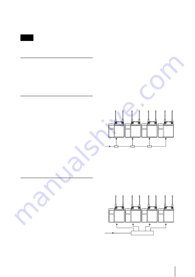
There are two types of systems for
synchronization using the master word
clock signal.
System example 1
The master word clock signal is split using
the T-shaped BNC splitter.
One of the devices including the
DWR-S01D must be terminated.
For details on how to terminate the word sync signal
on the DWR-S01D, refer to the Operating
Instructions supplied with the DWR-S01D.
a) 75-ohm termination setting: OFF
b) 75-ohm termination setting: ON
c) Master word clock signal
System example 2
The master word clock signal is supplied to
each device using the distributor. All the
devices must be terminated.
a) 75-ohm termination setting: ON
b) Master word clock signal
c) Word sync signal distributor
Note
a)
a)
a)
b)
c)
c)
b)
a)
a)
a)
a)


