background image

2-8E

2-15.CIRCUIT BOARDS LOCATION

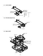
SW-385 board

IF-099 board

(SWITCH)

(IF COM)

PL-032 board

*NC665P only
(LED)

FR-197 board
(FUNCTION SW)

MD-94 board
(MD INTERFACE)

DV-034 board
(CONNECTOR)

MB-108 board
DVD/CD RF AMP, DIGITAL SERVO, 
MOTOR DRIVE, AV DECODER, 
SDRAM, SYSTEM CONTROL, 
AUDIO DAC, PLL, I/P CONVERTER, 
VIDEO ENCODER

AV-072 board
(AUDIO/VIDEO OUT)

ER-14 board
(LINE1 OUT)

SE-130 board
(SENSOR)

POWER BLOCK
(SWITCHING REGULATOR)

Содержание DVP-NC625

Страница 1: ... 75 ohms DIGITAL OUT OPTICAL Optical output jack 18 dBm wave length 660nm NC625 SP AUS NC665P CND COMPONENT VIDEO OUT Y PB PR CB CR Phono jack Y 1 0Vp p PB PR CB CR 0 7Vp p 75 ohms Y 1 0 0 1 Vp p Cb 646 50mVp p Cr 646 50mVp p NC625 US CND NC665P US CND R G B 700 50Vp p NC625 UK AEP LINE OUT VIDEO Phono jack 1 0 Vp p 75 ohms S VIDEO OUT 4 pin mini DIN Y 1 0Vp p C 0 3 Vp p PAL 0 286 Vp p NTSC 75 ohm...

Страница 2: ...lead free mark LF indicating the solder contains no lead Caution Some printed circuit boards may not come printed with the lead free mark due to their particular size LEAD FREE MARK Unleaded solder has the following characteristics Unleaded solder melts at a temperature about 40 C higher than ordinary solder Ordinary soldering irons can be used but the iron tip has to be applied to the solder join...

Страница 3: ...OM PARENTAL CONTROL PARENTAL CONTROL 1 13 Controlling Your TV with the Supplied Remote 1 14 Settings and Adjustments 1 15 Using the Setup Display 1 15 Setting the Display or Sound Track Language LANGUAGE SETUP 1 15 Settings for the Display SCREEN SETUP 1 15 Custom Settings CUSTOM SETUP 1 15 Settings for the Sound AUDIO SETUP 1 16 Additional Information 1 16 Troubleshooting 1 16 Self diagnosis Func...

Страница 4: ...nosis 6 1 6 4 Drive Auto Adjustment 6 5 6 5 Drive Manual Operation 6 7 6 6 Mecha Aging 6 11 6 7 Emergency History 6 11 6 8 Version Infromation 6 11 6 9 Video Level Adjustment 6 11 6 10 If Con Self Diagnostic Function 6 12 6 11 Troubleshooting 6 19 6 12 Mechanism Test Mode Adjustment 6 22 6 12 1 How to enter the mechanism test mode 6 22 6 12 2 Types of the mechanism test mode 6 22 6 12 3 Descriptio...

Страница 5: ... cam gear in the direction of the arrow A See Fig 2 Two tapping screws Two tapping screws Three screws B3 A 3 NOTE ON REMOVING THE TABLE ASS Y 1 Remove the two screws See Fig 3 Cam gear Table Hole A Screw M2 6 8 Screw M2 6 8 2 Remove the two Plates guide in the direction of the arrows A and B 3 Remove the Table ass y in the direction of the arrow C 4 Remove the Flexible flat cable See Fig 4 Plate ...

Страница 6: ...oder and mount the gear swing See Fig 6 4 Align triangle mark of the chassis with the groove of the gear swing Gear chuck Gear swing Gear swing Boss Groove Align triangle mark of the chassis with the groove of the gear swing 5 Mount the gear idler while aligning the engagement of the gear swing and the gear chuck See Fig 7 Gear idler Gear idler Gear chuck Gear swing Engagement the gear swing and t...

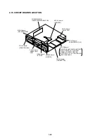
Страница 7: ... 122 A FFC 11P J 6090 120 A Harness 6P J 6090 126 A CK 120 board J 6090 127 A Stand CK 121 board J 6090 132 A Five flexible flat cables Jig 4 Set the CK 120 board in the place where the MB 108 board is removed as shown in Fig 10 Connector CN101 Stand with CK 121 board MB 108 board Two screws B3 Connector CN109 Board to board connector CN111 CK 120 board Four screws B3 Flexible flat cable FMO 6 CN1...

Страница 8: ...exible flat cable and the harness as shown in Fig 12 Connector CN304 Connector CN203 Harness 6P CN102 Flexible flat cable FFC 25P CN601 Connector CN102 MB 108 Connector CN104 Connector CN301 Flexible flat cable FFC 9P CN204 Flexible flat cable FFC 26P CN203 7 Set is finished Fig 11 Fig 12 ...

Страница 9: ... 9P B to B Connector 9P FFC 26P Used the set FFC 9P Used the set FFC 11P Used the set HARNESS 6P HARNESS 6P Used the set FFC 26P FFC 9P FFC 11P FFC15P FFC25P CN101 CN102 CN103 CN104 CN107 CN108 CN110 CN203 CN204 CN201 CN102 CN111 CN109 CN308 CN311 CN301 CN112 CN201 CN202 CN101 CN601 CN201 6 CONNECTION OF SERVICE JIG ...

Страница 10: ... 10 DVP NC625 NC665P MEMO 10E ...

Страница 11: ... player cannot play the following discs All CD ROMs including PHOTO CDs CD Rs CD RWs other than those recorded in the following formats music CD format video CD format Icon Meaning Functions available for DVD VIDEOs and DVD RWs DVD Rs in video mode or DVD RWs DVD Rs Functions available for DVD RWs in VR Video Recording mode Functions available for VIDEO CDs Super VCDs or CD Rs CD RWs in video CD f...

Страница 12: ... R DISC SKIP button 27 S ANGLE button 53 T SUR surround button 51 U PICTURE NAVI picture navigation button 44 V REPEAT button 39 W INSTANT SEARCH STEP button 28 41 X INSTANT REPLAY STEP button 28 41 Y x STOP button 28 Z ENTER button 24 wj O RETURN button 29 wk MENU button 31 33 Use the tactile dot as a reference when operating the player 12 Guide to the Control Menu Display Use the Control Menu to...

Страница 13: ...E page 55 Adjusts the video signal from the player You can select the picture quality that best suits the program you are watching DIGITAL VIDEO ENHANCER page 56 Exaggerates the outline of the image to produce a sharper picture PICTURE NAVIGATION page 44 Divides the screen into 9 subscreens to help you find the scene you want quickly t 15 Hookups Hookups Hooking Up the Player Follow Steps 1 to 6 t...

Страница 14: ...ORMAL INTERLACE Select this when you are connected to a standard Interlace format TV PROGRESSIVE AUTO Select this when you are connected to a progressive TV This will automatically detect if you are playing Film based or Video based software and convert the signal to the appropriate conversion mode Normally select this position when you are connected to a progressive TV PROGRESSIVE VIDEO Select th...

Страница 15: ...g a Dolby Digital or DTS decoder and 6 speakers This connection will allow you to use the Dolby Digital or DTS decoder function of your AV amplifier receiver Note After you have completed the connection be sure to set DOLBY DIGITAL to DOLBY DIGITAL and DTS to ON in Quick Setup page 24 D Front R Front L Rear R AV amplifier receiver having a decoder Subwoofer Center Coaxial digital cord not supplied...

Страница 16: ...the player and place a disc on the disc tray To place other discs on the tray press DISC SKIP and place the discs in the order you want to play them Each time you press DISC SKIP the disc tray turns so you can place the discs on the empty compartments The player plays from the last disc placed on the tray 5 Press H The disc tray closes and the player starts playback continuous play Adjust the volu...

Страница 17: ...ame point the next time you insert the same disc The player remembers the stopped point of the disc even after you play other discs in the disc tray Resume playback points for up to 6 different DVD VIDEO VIDEO CD discs remain in memory even if you disconnect the power cord When you store a resume playback point for the 7th disc the resume playback point for the first disc is deleted z Hints To pla...

Страница 18: ...O V A J A Z Z 1 90 0 1 S H E I S S P E C I A L 0 2 A L L Y O U N E E D I S 0 3 S P I C Y L I F E 0 4 H A P P Y H O U R 0 5 R I V E R S I D E 0 6 5 0 7 T A K E T I M E T A K E T I M E 35 Playing Discs The playback order of MP3 audio tracks The playback order of albums and tracks recorded on a DATA CD is as follows Structure of disc contents When you insert a DATA CD and press H the numbered tracks ...

Страница 19: ...E OFF DVD VIDEO PLAY 39 Playing Discs 4 Press ENTER Shuffle Play starts You can select DISC in All Discs mode only To return to normal play Press CLEAR or select OFF in step 2 To turn off the control menu Press DISPLAY repeatedly until the Control Menu is turned off z Hints You can set Shuffle Play while the player is stopped After selecting the SHUFFLE option press H Shuffle Play starts Up to 96 ...

Страница 20: ... DISC TRACK INDEX When playing a DATA CD MP3 audio DISC ALBUM TRACK Example when you select CHAPTER is selected refers to a number The number in parentheses indicates the total number of titles chapters tracks indexes or scenes 3 Press ENTER changes to 4 Press X x or the number buttons to select the title chapter track index or scene number you want to search If you make a mistake Cancel the numbe...

Страница 21: ...ding on the type of disc being played the DVD CD text or track name may not be displayed The player can only display the first level of the DVD CD text such as the disc name or title Playing time of MP3 audio tracks may not be displayed correctly Playing time of the current title Remaining time of the current title Playing time of the current chapter Remaining time of the current chapter Text Curr...

Страница 22: ...l LFE Low Frequency Effect signal z Hint For Dolby Digital and DTS LFE is always enclosed in a solid line regardless of the LFE signal component being output Note If DTS is set to OFF in AUDIO SETUP page 68 the DTS track selection option will not appear on the screen even if the disc contains DTS tracks DVD VIDEO 1 ENGLISH 1 8 3 4 1 2 2 7 T 1 3 2 5 5 1 L R C DOLBY DIGITAL 3 2 1 PROGRAM FORMAT LFE ...

Страница 23: ...also select SUBTITLE from the Control Menu page 12 Note Depending on the DVD VIDEO you may not be able to change the subtitles even if multilingual subtitles are recorded on it You also may not be able to turn them off 2 SUBTITLE 1 ENGLISH 54 Adjusting the Picture Quality BNR The Block Noise Reduction BNR function adjusts the picture quality by reducing the block noise or mosaic like patterns that...

Страница 24: ...put the password to play the disc Parental Control limited playback Playback of some DVD VIDEOs can be limited according to a predetermined level such as the age of the users The PARENTAL CONTROL function allows you to set a playback limitation level 1 Press DISPLAY while the player is in stop mode The Control Menu appears 2 Press X x to select PARENTAL CONTROL then press ENTER The options for PAR...

Страница 25: ...ic 19 Philips 21 RCA 10 Samsung 20 Sanyo 11 Sharp 18 Toshiba 07 Zenith 15 63 Settings and Adjustments Settings and Adjustments Using the Setup Display By using the Setup Display you can make various adjustments to items such as picture and sound You can also set a language for the subtitles and the Setup Display among other things For details on each Setup Display item see pages from 64 to 68 Note...

Страница 26: ...SCREEN SETUP in the Setup Display To use the display see Using the Setup Display on page 63 The default settings are underlined TV TYPE Selects the aspect ratio of the connected TV 4 3 standard or wide Note Depending on the DVD 4 3 LETTER BOX may be selected automatically instead of 4 3 PAN SCAN or vice versa SCREEN SAVER The screen saver image appears when you leave the player in pause or stop mo...

Страница 27: ...page 31 Multilingual subtitles are not recorded on the DVD being played The DVD prohibits the changing of the subtitles The angles cannot be changed Try using the DVD s menu instead of the direct selection button on the remote page 31 Multi angles are not recorded on the DVD being played The angle can only be changed when the ANGLE indicator lights up on the front panel display page 9 The DVD proh...

Страница 28: ...528 Thai 1529 Tigrinya 1531 Turkmen 1532 Tagalog 1534 Setswana 1535 Tonga 1538 Turkish 1539 Tsonga 1540 Tatar 1543 Twi 1557 Ukrainian 1564 Urdu 1572 Uzbek 1581 Vietnamese 1587 Volapük 1613 Wolof 1632 Xhosa 1665 Yoruba 1684 Chinese 1697 Zulu 1703 Not specified 73 Additional Information Film based software Video based software page 18 DVDs can be classified as Film based or Video based software Film...

Страница 29: ...e numerical order given IF 099 FR 197 boards Page 2 6 Loading motor ass y M901 Page 2 5 Optical pick up Page 2 5 Table ass y Page 2 4 AV 072 board Page 2 4 ER 14 board AEP UK Page 2 4 Front panel section Page 2 2 Rear panel section Page 2 2 MB 108 board Page 2 3 DV 034 board Page 2 3 Power block Page 2 6 Upper case Page 2 1 Set This set can be disassembled in the order shown below ...

Страница 30: ...le FMV 20 CN203 Connector CN101 Two screws B3 Screw B3 Screw B3 Screw B3 Flexible flat cable FFC FDS 003 CN308 Claw Cla Connector CN2 Connector CN471 Connector CN402 Connector CN306 Cover Tray w Two screws B3 Two scre Harness FV 121 Harness PF 134 ws B3 Front panel section Connector CN202 AV 072 Board Connector CN403 ...

Страница 31: ...3 Pull the tray in the direction of the arrow Flexible flat cable FDS 003 CN308 B A A B 2 6 DV 034 BOARD Connector CN102 Board to board connector CN101 MB 108 board Pull the tray in the direction of the arrow Insert a flat head screwdriver into a hole at the bottom and rotate the cam gear in the direction of the arrow Four screws B3 Flexible flat cable FMO 6 9P CN204 Flexible flat cable FMM 42 26P...

Страница 32: ... Flexible flat cable FMO 6 CN204 Flexible flat cable FMM 42 CN203 2 7 AV 072 BOARD AV 072 board Six screws B3 NC665P Five screws B3 NC625 Screw Qty Flexible flat cable FAE 10 CN102 EC1 EC2 CEK USA Canada 5 PX3 5 ECI CEK 4 MX2 E32 5 SP6 6 AU2 6 ER 14 board Two screws B3 Flexible flat cable FAE 10 CN901 ...

Страница 33: ...PICK UP MD 94 board Belt timing Connector CN004 Loading motor assembly M901 Claw Claws Screw M2 6 4 Screw M2 6 4 Screw M2 6 8 Flexible flat cable FMM 42 26P Optical pick up Three step screws Flexible flat cable FMO 6 9P Two screws B3 Chuck assy ...

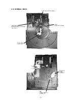
Страница 34: ...LOCK Front panel Harness FP 176 3p CN701 Flexib Screw B2 6 x 8 BVTP 4 951 620 01 le flat cab NC625 NC665P le FDS 003 2 13 IF 099 AND FR 197 BOARDS Connector CN1 Power block Holder PS Two claws Harness CN2 Two screws B3 ...

Страница 35: ...AL VIEWS Optical pick up KHM 290AA Service assembly A 6061 908 A TD unit ass y A 6060 640 A PH102 on the SE 130 board PH101 on the SE 130 board M901 Loading motor ass y X 3952 378 1 Encoder ass y loading X 3952 380 1 ...

Страница 36: ... FR 197 board FUNCTION SW MD 94 board MD INTERFACE DV 034 board CONNECTOR MB 108 board DVD CD RF AMP DIGITAL SERVO MOTOR DRIVE AV DECODER SDRAM SYSTEM CONTROL AUDIO DAC PLL I P CONVERTER VIDEO ENCODER AV 072 board AUDIO VIDEO OUT ER 14 board LINE1 OUT SE 130 board SENSOR POWER BLOCK SWITCHING REGULATOR ...

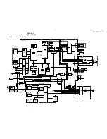
Страница 37: ...EO BUFFER VIDEO BUFFER SELECT SWITCH SPDIF IC204 AUDIO D A CONVERTER IC201 AUDIO AMP INLIMIT SENSOR ROTARY ENCODER DV 034 BOARD SE 130 BOARD M M TURNTABLE MOTOR FUNCTION KEY PROG LED SW 3 5V 11V AU 5V 5V EVER 3 5V SW 3 5V SW 15 5V 1 8V SWITCHING REG AC IN V Y C R G B LINE1 RGB TV CNJ902 PB COMPONENT VIDEO OUT Y PR LINE OUT VIDEO S VIDEO OUT L R LINE OUT AUDIO 1 OPTICAL DIGITAL OUT COAXIAL J201 D11...

Страница 38: ...E CS5X CKSW1 XDRVMUTE XSDPIT OCSW1 XLDON XSDPCS CKSW1 DREQ0 INTO DACK0 CS2X CS3X DREQ1 DACK1 DREQ0 XAVDIT DACK0 XAVDCS2 XAVDCS3 DREQ1 DACK1 VIDEO AUDIO SEE PAGE 3 9 to 3 14 SIGNAL PROCESSOR SEE PAGE 3 7 RF SERVO SEE PAGE 3 5 05 33MARP 512FSAVD X102 27MHz 33 1OUT FSEL 512FS2CH XFRRST 59 CS1X 72 XWRL 84 SRAMWE 29 SO1 SO1 30 SC1 SC1 79 XDACS XDACS INT1 CS4X XWAIT 35 XRST XRST VIDEO AUDIO SEE PAGE 3 9...

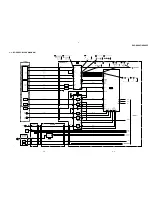
Страница 39: ... DVD LD 26 19 Q202 CD LD DRIVE CD LD CD LD VR SLA SLB SPM INLIM TRK 127 ADC3 FCS PS TSD M 40 42 43 VREF 3 3V LDON GIO6 SDI GIO7 SDO GIO8 SCK GIO13 XSDPIT XSDPCS XRST XDRVMUTE SIGO FE TE PI SSDFCTI SS MON MDSO MDPO SPMUTE SLDA SLDB LMP LMM TSD LMCTL TDRV FDRV SPFG SLE 159 161 162 167 A 12 D 11 C 10 B 9 E 17 F 13 15x7 8 5 4 IC303 TURNTABLE MOTOR DRIVE 10 CN201 LDM LM LOADING MOTOR M M 1 2 CKSW1 OCSW...

Страница 40: ... 0 7 HD 8 15 XRD XWRH RSTn DM ACK1 DM REQ1 DM ACK0 DM REQ0 ACLK HAD23 HAD22 CLKI SCLKI 200 199 HWAITOn HIREQO HA 0 21 HD 0 15 HA 0 21 HD 0 15 XRST 512FSAVD 33MARP XWRH XRD TRST XARPIT XARPCS XWAIT XAVDCS2 XAVDCS3 27MAVD XAVDIT DREQ0 DACK0 DREQ1 DACK1 XWR XRD XINT XCS XWAT CLKIN 25 ACH34 24 70 ACH12 VREFI ACH12 30 DO SPDIF 173 172 TDI LAND FOR J TAG TMS 171 TRST TDO 174 TCK TCK 175 TDO TDI TMS TRST...

Страница 41: ... CSN 6 PDN 5 CCLK 7 CDTI 8 17 CN601 3 3 11 ALT 15 5 ART 21 3 ART 23 4 LMUTE 22 6 RMUTE 20 2 MAMUTE 24 MB 108 BOARD 6 6 SEE PAGE 4 19 AV 072 BOARD 2 2 SEE PAGE 4 29 EXCEPT EC1 CEK AEP UK EC1 CEK 10 OPTICAL IC204 DIGITAL OUT COAXIAL SPDIF 16 CN101 2 2 CN202 2 SPDIF 1 D IN ACH12 LRCK BCK SO1 SC1 XRST 512FS2CH XDACS MAMUTE D202 Q211 BUFFER Q207 MUTE Q208 MUTE 1 7 D203 Q202 204 205 MUTE DRIVE Q206 209 ...

Страница 42: ...XCEPT AEP UK LINE OUT VIDEO 1 VIDEO Y C S VIDEO OUT VIDEO IN Y IN C IN MUTE1 Y IN Cb IN Cr IN MUTE2 VIDEO OUT Y OUT 13 25 IC901 VIDEO BUFFER SELECT SWITCH V IN 15 Y IN V Y OUT 5 34 C IN 7 R IN R C OUT 9 29 G IN 11 B IN 33 MUTE1 24 MUTE3 28 MUTE2 30 SW1 12 SW2 G OUT V Y R C G B 27 B OUT C OUT Y OUT Cb OUT Cr OUT V Y C Y V Y C R G B Cb Cr 21 17 5 19 3 13 9 15 7 11 10 11 12 13 19 15 21 Q104 105 WIDE ...

Страница 43: ... J104 Y OUT C OUT Y OUT Cr IN Y Cb Cr 7 11 9 5 3 1 38 44 IC504 VIDEO ENCODER S 2 9 DAC A DAC E 43 42 39 37 DAC B DAC C DAC D DAC F 53 55 58 62 2 9 12 13 14 18 26 30 32 63 PO 0 7 22 25 28 31 41 45 48 52 56 60 63 67 Y 0 9 CBCR 0 9 40 P_Y 0 9 P_C 0 9 22 21 33 SDA SCL SRN IC503 16M SDRAM 110 113 116 119 122 125 129 132 HD 0 15 DQ 0 15 80 83 86 89 94 97 103 AO 0 11 MA 0 11 MCLOCK PO 2 9 YO 0 9 CO 0 9 C...

Страница 44: ...UT SEG 1 21 DIG 1 18 X401 8MHz ND401 VACUUM FLUORESCENT DISPLAYS 1 IC406 REMOTE COMMANDER RECEIVER CN501 CN404 CN405 7 9 CN407 SC0 SI0 SO0 XIFBUSY XIFCS XFRRST SC0 SI0 SO0 IFBSY XIFCS XFRRST AD1 AD2 TVS 1 VOUT 8 RST 34 AD1 35 AD2 VMUTE XIN XOUT POWER 5 4 3 2 S604 S605 S603 S602 S601 37 AD4 36 AD3 S610 S607 CN603 CN401 AD3 1 LED 1 AD4 3 5 5 3 IC404 3 4 Vp p 8 MHz S606 S608 S609 1 PVEQ I ALL LOAD NC...

Страница 45: ...6 IC2 PHOTO COUPLER IC1 SWITCHING CONTROL 10 11 2 9 13 1 2 Q401 Q1 F301 F101 FL1 2 LINE FILTER L501 Q402 POWER CONTROL L205 D201 L201 L301 D301 L101 IC303 SHUNT REG EVER 11V SW 5V SW 3 5V EVER 5V EVER 15 5V P CONT D201 Q301 SW 11V SWITCHING REGULATOR DPS 21BPA NC625 US CND MX NC665P US CND L301 TO IF 99 PAGE 4 39 ...

Страница 46: ...C101 PHOTO COUPLER IC101 SWITCH 10 11 2 9 13 1 2 Q301 L101 102 LINE FILTER D204 Q205 POWER CONTROL L205 D201 L201 L301 D301 L202 L204 IC202 SHUNT REG EVER 11V SW 5V SW 3 5V EVER 5V EVER 15 5V P CONT F201 F202 L203 L206 Q204 SW 11V SWITCHING REGULATOR ETXNY410M0F NC625 E AEP UK SP AUS TO IF 99 PAGE 3 39 3 20 3 19 ...

Страница 47: ... SERVO DSP 16M SDRAM 16M SDRAM NC 625 US CND PX only AUDIO D A CONVERTER DVD CD RF AMP DIGITAL SERVO OPTICAL DIGITAL OUT D201 CN102 CN801 11V 11V 5V 5V MUTE A IC403 AV DECODER IC503 IC404 IF CON 3 3 MNT CN101 CN102 FL110 FL105 FL104 3 5V 5V 1 8V 11V RST PONCHK PCONT VDD POWER VREF VCC IC202 IC505 IC501 IC504 IC502 4 1 1 1 2 4 8 7 3 1 5 4 1 1 5 4 6 5 17 3 5V REG FILTER FILTER FILTER FL109 FILTER SD...

Страница 48: ...DVP NC625 NC665P 1 A B C D E F G H I J 2 12 13 11 10 9 8 7 6 5 4 3 14 15 4 1 4 2 SECTION 4 PRINTED WIRING BOARDS AND SCHEMATIC DIAGRAMS 4 1 FRAME SCHEMATIC DIAGRAM FRAME SCHEMATIC DIAGRAM ...

Страница 49: ...s New parts must be attached after removal of chip Be careful not to heat the minus side of tantalum capacitor because it is damaged by the heat All variable and adjustable resistors have characteristic curve B unless otherwise noted non flammable resistor fusible resistor panel designation f internal component adjustment for repair B Line B Line Circled numbers refer to waveforms Voltages are dc ...

Страница 50: ...6mVp p 6 35usec IC403 yd 20 625mVp p 6 8usec IC403 yg 21 1 1Vp p 33 5usec IC403 22 3 3Vp p 38nsec IC502 r 23 3 3Vp p 36nsec IC502 24 3 3Vp p 18 3nsec IC504 es 25 3 3Vp p 36nsec IC504 ej 26 483mVp p 63 5nsec IC504 ek 27 633mVp p 63 5usec IC504 el 28 131Vp p 63 5usec IC504 rs 29 508Vp p 280nsec IC504 rd 30 979mVp p 63 5usec IC504 rf 31 1 08Vp p 63 4usec IC601 1 32 3 3Vp p 42nsec 3 3Vp p 30nsec 0 47V...

Страница 51: ...rd SWITCH IF COM PL 032 board NC665P only LED FR 197 board FUNCTION SW MD 94 board MD INTERFACE DV 034 board CONNECTOR MB 108 board DVD CD RF AMP DIGITAL SERVO MOTOR DRIVE AV DECODER SDRAM SYSTEM CONTROL AUDIO DAC PLL I P CONVERTER VIDEO ENCODER AV 072 board AUDIO VIDEO OUT ER 14 board LINE1 OUT SE 130 board SENSOR POWER BLOCK SWITCHING REGULATOR MB 108 BOARD A SIDE IC104 B 6 IC301 B 3 IC302 B 2 I...

Страница 52: ... board Refer to page 4 5 for waveform The components identified by mark or dotted line with mark are critical for safety Replace only with part number specified Les composants identifiés par une marque sont critiques pour la sécurité Ne les remplacer que par une pièce portant le numéro spécifié MB 108 BOARD 1 6 SYSTEM CONTROL REF NO 1000 SERIES XX MARK NO MOUNT NO MARK REC PB MODE ...

Страница 53: ...PEED AND PHASE TRACKING SERVO DVD CD CDV SLED SERVO DVD CD FOCUS SERVO SKEW SERVO DVD CD 2 0 2 0 2 0 2 0 2 0 2 0 0 2 0 2 0 2 0 2 0 2 0 2 0 2 0 2 0 0 01 3 4 3 4 0 0 3 4 3 4 3 4 3 4 11 0 5 3 5 3 0 05 6 0 5 0 5 3 5 3 5 4 5 2 0 05 5 3 5 3 5 3 0 5 3 11 0 5 3 3 4 2 0 2 0 2 0 5 0 2 4 3 2 3 2 2 0 0 3 2 3 2 0 2 0 0 3 3 0 03 0 03 2 4 0 03 0 03 0 02 2 5 0 03 0 03 3 0 0 1 5 0 5 0 0 3 0 0 1 0 0 1 0 4 4 3 1 2 1...

Страница 54: ...0 2 0 4 0 5 0 3 0 2 0 2 0 2 0 2 0 1 3 3 0 0 0 2 0 3 0 2 0 0 5 2 0 2 0 0 2 0 3 1 0 2 0 1 0 2 4 3 3 0 2 0 2 0 2 0 0 03 2 0 2 0 3 3 0 04 0 5 0 3 3 0 1 0 0 3 4 3 0 2 0 3 3 2 0 0 1 0 0 3 4 0 3 4 0 0 0 0 2 0 2 0 0 2 0 2 2 0 0 1 0 0 3 4 2 0 2 1 1 4 1 1 1 4 1 0 1 0 2 0 3 4 2 0 0 0 2 0 0 1 0 2 0 2 0 0 1 5 0 3 4 3 4 0 0 3 4 3 4 3 0 3 4 3 4 3 4 0 3 3 0 0 0 2 0 3 4 3 0 2 0 0 1 3 1 7 2 0 3 4 3 3 3 0 3 2 3 3 3 ...

Страница 55: ...1 2 1 5 1 5 0 2 0 2 0 0 2 0 1 4 3 4 2 0 1 5 0 1 0 2 0 3 4 0 1 3 1 3 0 3 0 3 1 1 0 0 1 0 1 1 0 2 0 1 0 3 4 0 0 0 4 3 3 4 0 2 1 2 2 3 4 2 0 1 0 0 1 0 1 0 0 5 2 1 3 4 2 0 1 1 1 0 1 1 1 3 1 0 1 2 2 3 1 3 0 0 1 0 1 0 3 3 3 0 0 0 0 3 0 3 4 4 0 3 3 3 3 2 0 0 0 03 0 0 3 0 04 4 0 0 1 2 4 0 3 3 0 0 3 3 1 0 1 3 0 1 0 1 0 1 4 1 2 0 2 0 1 0 1 0 1 3 2 0 2 0 2 0 2 0 0 0 2 0 1 0 1 0 2 0 0 2 0 2 0 0 0 0 3 4 2 0 2 ...

Страница 56: ...TER MB 108 5 6 For Schematic Diagram Refer to page 4 7 for printed wiring board of MB 108 board Refer to page 4 5 for waveform MB 108 BOARD 5 6 1 P CONVERTER REF NO 5000 SERIES XX MARK NO MOUNT NO MARK PB MODE SIGNAL PATH VIDEO SIGNAL CHROMA PB Y Y CHROMA AUDIO SIGNAL 23 24 25 26 27 29 28 30 31 ...

Страница 57: ...MB 108 6 6 For Schematic Diagram Refer to page 4 7 for printed wiring board of MB 108 board Refer to page 4 5 for waveform MB 108 BOARD 6 6 AUDIO DAC PLL REF NO 6000 SERIES XX MARK NO MOUNT NO MARK PB MODE 0 3 4 3 4 3 4 2 0 1 2 2 0 2 0 5 0 5 0 5 0 0 2 4 2 4 2 4 2 4 1 TO AV 072 BOARD CN203 PAGE 4 29 ...

Страница 58: ...1 25V CHIP XX C517 XX XX XX XX XX XX 0 01 25V CHIP 0 01 25V CHIP XX C518 XX XX XX XX XX XX 0 1 16V CHIP 0 1 16V CHIP XX C520 XX XX XX XX XX XX 47 6 3V CHIP 47 6 3V XX C521 XX XX XX XX XX XX 0 1 16V CHIP 0 1 16V CHIP XX C526 XX XX XX XX XX XX 0 1 16V CHIP 0 1 16V CHIP XX C527 XX XX XX XX XX XX 0 1 16V CHIP 0 1 16V CHIP XX C528 XX XX XX XX XX XX 0 01 25V CHIP 0 01 25V CHIP XX C529 XX XX XX XX XX XX ...

Страница 59: ... XX XX IC504 XX XX XX XX XX XX ADV7300AKST ADV7300AKST XX IC505 XX XX XX XX XX XX TK11133CSCL G TK11133CSCL G XX R114 0 0 0 0 0 0 470 CHIP 470 CHIP 0 CHIP R164 470 CHIP 470 CHIP 12K CHIP 22K CHIP 220K CHIP 2 2K CHIP XX XX XX R166 12K CHIP 12K CHIP 12K CHIP 12K CHIP 12K CHIP 12K CHIP 6 8K CHIP 6 8K CHIP 12K CHIP R169 12K CHIP 12K CHIP 47K CHIP 12K CHIP 12K CHIP 22K CHIP XX XX XX R401 0 0 0 0 0 0 XX...

Страница 60: ... DV 034 board CONNECTOR MB 108 board DVD CD RF AMP DIGITAL SERVO MOTOR DRIVE AV DECODER SDRAM SYSTEM CONTROL AUDIO DAC PLL I P CONVERTER VIDEO ENCODER AV 072 board AUDIO VIDEO OUT ER 14 board LINE1 OUT SE 130 board SENSOR POWER BLOCK SWITCHING REGULATOR 1 2 3 4 5 D C B A 1 2 3 4 5 D C B A AV 072 BOARD SIDE B A SIDE IC204 D 4 B SIDE IC102 C 4 IC103 A 5 IC201 C 2 IC203 B 2 Q104 D 5 Q105 D 4 Q106 C 3...

Страница 61: ...IDEO OUT AV 072 1 2 For Schematic Diagram Refer to page 4 25 for printed wiring board of AV 072 board Refer to page 4 5 for waveform AV 072 B_ B B_ AV 072 BOARD 1 2 VIDEO OUT REF NO 1000 SERIES XX MARK NO MOUNT NO MARK PB MODE SIGNAL PATH VIDEO SIGNAL CHROMA PB Y Y CHROMA AUDIO SIGNAL ...

Страница 62: ...30 AUDIO OUT AV 072 2 2 AV 072 BOARD 2 2 AUDIO OUT REF NO 2000 SERIES XX MARK NO MOUNT NO MARK PB MODE SIGNAL PATH VIDEO SIGNAL CHROMA PB Y Y CHROMA AUDIO SIGNAL For Schematic Diagram Refer to page 4 25 for printed wiring board of AV 072 board Refer to page 4 5 for waveform AV 072 ...

Страница 63: ...P XX JACK PIN 3P JACK PIN 3P JACK PIN 3P JACK PIN 3P Q106 XX XX 2SA1162 YG TE85L XX XX XX XX Q206 XX XX MUN2213T1 XX XX XX XX Q209 XX XX UN2217 TX XX XX XX XX Q210 XX XX MSB709 RT1 XX XX XX XX R122 XX XX 1K XX XX XX XX R126 68 CHIP 68 CHIP XX 68 CHIP 68 CHIP 68 CHIP 68 CHIP R127 68 CHIP 68 CHIP XX 68 CHIP 68 CHIP 68 CHIP 68 CHIP R128 68 CHIP 68 CHIP XX 68 CHIP 68 CHIP 68 CHIP 68 CHIP R214 XX XX 4 ...

Страница 64: ...B 3 D918 B 3 D919 B 2 D920 B 2 D929 B 3 D930 B 4 IC901 A 3 Q901 A 4 Q902 A 4 Q903 A 4 Q906 A 4 Q907 B 4 Q908 B 4 SW 385 board IF 099 board SWITCH IF COM PL 032 board NC665P only LED FR 197 board FUNCTION SW MD 94 board MD INTERFACE DV 034 board CONNECTOR MB 108 board DVD CD RF AMP DIGITAL SERVO MOTOR DRIVE AV DECODER SDRAM SYSTEM CONTROL AUDIO DAC PLL I P CONVERTER VIDEO ENCODER AV 072 board AUDIO...

Страница 65: ... L IN 6 B_OUT 7 FUNCTION_SW_OUT 8 GND E 9 AVLINKO 10 G_OUT 11 N C 12 GND E 13 GND E 14 R C_OUT 15 BLANKING_OUT 16 GND E 17 GND E 18 V Y_OUT 19 V_IN 20 GND E 21 XX R941 JL950 1800 R914 R958 0uH JL949 330 R911 JL947 47k R905 JL944 100p C962 68 R929 JL934 JL935 470 R924 100uH L905 FB908 0uH XX R940 XX R901 2SD601A QRS TX Q902 1800 R917 HZM6 8ZWA1TL D919 680 R915 UN2111 TX Q907 JL938 XX R919 JL925 JL9...

Страница 66: ... IC404 C 4 IC406 A 7 IC407 B 6 IC408 C 2 IC473 C 8 IC474 C 8 Q472 B 9 Q473 B 8 SW 385 board IF 099 board SWITCH IF COM PL 032 board NC665P only LED FR 197 board FUNCTION SW MD 94 board MD INTERFACE DV 034 board CONNECTOR MB 108 board DVD CD RF AMP DIGITAL SERVO MOTOR DRIVE AV DECODER SDRAM SYSTEM CONTROL AUDIO DAC PLL I P CONVERTER VIDEO ENCODER AV 072 board AUDIO VIDEO OUT ER 14 board LINE1 OUT S...

Страница 67: ... 8 7 6 5 4 3 14 15 4 39 4 40 IF 099 BOARD 1 2 IF COM REF NO SERIES XX MARK NO MOUNT NO MARK REC PB MODE Cannot be measured IF COM IF 099 For Schematic Diagram Refer to page 4 37 for printed wiring board of IF 099 board Refer to page 4 5 for waveform IF 099 ...

Страница 68: ... XX MARK NO MOUNT NO MARK REC PB MODE Cannot be measured For Schematic Diagram Refer to page 4 37 for printed wiring board of IF 099 board Refer to page 4 5 for waveform IF 099 NC665P US NC665P US CND NC625 AUS PX CND US NC625 SP E MX UK AEP AUS R430 XX XX 0 0 R431 100K CHIP 100K CHIP XX XX IF 099 BOARD differential Part List 1 2 2 2 ...

Страница 69: ...099 board SWITCH IF COM PL 032 board NC665P only LED FR 197 board FUNCTION SW MD 94 board MD INTERFACE DV 034 board CONNECTOR MB 108 board DVD CD RF AMP DIGITAL SERVO MOTOR DRIVE AV DECODER SDRAM SYSTEM CONTROL AUDIO DAC PLL I P CONVERTER VIDEO ENCODER AV 072 board AUDIO VIDEO OUT ER 14 board LINE1 OUT SE 130 board SENSOR POWER BLOCK SWITCHING REGULATOR PL 032 BOARD A SIDE D701 A 3 B SIDE D701 A 2...

Страница 70: ... 4 46 PL 032 BOARD LED REF NO SERIES XX MARK NO MOUNT NO MARK REC PB MODE Cannot be measured For Schematic Diagram Refer to page 4 43 for printed wiring boards of PL 032 SW 385 boards SW 385 BOARD SWITCH REF NO SERIES XX MARK NO MOUNT NO MARK REC PB MODE LED PL 032 SWITCH SW 385 ...

Страница 71: ...l Uses unleaded solder FR 197 BOARD SIDE A FR 197 BOARD SIDE B SW 385 board IF 099 board SWITCH IF COM PL 032 board NC665P only LED FR 197 board FUNCTION SW MD 94 board MD INTERFACE DV 034 board CONNECTOR MB 108 board DVD CD RF AMP DIGITAL SERVO MOTOR DRIVE AV DECODER SDRAM SYSTEM CONTROL AUDIO DAC PLL I P CONVERTER VIDEO ENCODER AV 072 board AUDIO VIDEO OUT ER 14 board LINE1 OUT SE 130 board SENS...

Страница 72: ...FR 197 BOARD FUNCTION SW REF NO SERIES XX MARK NO MOUNT NO MARK REC PB MODE For Schematic Diagram Refer to page 4 47 for printed wiring board of FR 197 board FR 197 BOARD differential Part List NC665P US NC665P US CND NC625 AUS PX CND US NC625 SP E MX UK AEP AUS CN602 HARNESS FP 176 HARNESS FP 176 XX XX ...

Страница 73: ...TOR DV 034 SW 385 board IF 099 board SWITCH IF COM PL 032 board NC665P only LED FR 197 board FUNCTION SW MD 94 board MD INTERFACE DV 034 board CONNECTOR MB 108 board DVD CD RF AMP DIGITAL SERVO MOTOR DRIVE AV DECODER SDRAM SYSTEM CONTROL AUDIO DAC PLL I P CONVERTER VIDEO ENCODER AV 072 board AUDIO VIDEO OUT ER 14 board LINE1 OUT SE 130 board SENSOR POWER BLOCK SWITCHING REGULATOR DV 034 BOARD A SI...

Страница 74: ...E F G H I J 2 12 13 11 10 9 8 7 6 5 4 3 14 15 4 53 4 54 CONNECTOR DV 034 DV 034 BOARD CONNECTOR REF NO SERIES XX MARK NO MOUNT NO MARK REC PB MODE For Schematic Diagram Refer to page 4 51 for printed wiring board of DV 034 board ...

Страница 75: ...sn t mounted in this model SE 130 BOARD MD 94 BOARD SW 385 board IF 099 board SWITCH IF COM PL 032 board NC665P only LED FR 197 board FUNCTION SW MD 94 board MD INTERFACE DV 034 board CONNECTOR MB 108 board DVD CD RF AMP DIGITAL SERVO MOTOR DRIVE AV DECODER SDRAM SYSTEM CONTROL AUDIO DAC PLL I P CONVERTER VIDEO ENCODER AV 072 board AUDIO VIDEO OUT ER 14 board LINE1 OUT SE 130 board SENSOR POWER BL...

Страница 76: ...L S001 4 NC1 5 NC2 1 COM 2 A 3 C 6P CN101 1 2 3 4 5 6 RPR 220C1N PH101 1 2 3 4 RPI 1391 2 PH102 1 2 4 3 2P CN102 1 2 OCSW2 OCSW1 CKSW1 SGND SENSOR LED TSENS DSENS LM LM TM TM OCSW1 CKSW1 SGND LM LM SENSORLED TSENS DSENS SGND TM TM M ROTARY ENCODER M001 LOADING MOTOR SGND TM TM TM SENSOR LED TM TSENS DSENS M TURN TABLE MOTOR SE 130 BOARD SENSOR REF NO 1000 SERIES XX MARK NO MOUNT For Schematic Diag...

Страница 77: ... C 5 Q203 A 7 Q204 B 6 Q205 C 7 Q301 C 7 D102 C 3 D103 C 4 D104 A 3 D105 A 3 D106 A 3 D107 A 3 D201 C 5 D202 B 6 D203 B 5 D204 A 5 D301 B 6 4 59 4 60 For printed wiring board There are a few cases that the part printed on this diagram isn t mounted in this model SW 385 board IF 099 board SWITCH IF COM PL 032 board NC665P only LED FR 197 board FUNCTION SW MD 94 board MD INTERFACE DV 034 board CONNE...

Страница 78: ... 2 12 13 11 10 9 8 7 6 5 4 3 14 15 For Schematic Diagram Refer to page 4 59 for printed wiring board of ETXNY410M0F board ETXNY410M0F BOARD SW REG REF NO 5000 SERIES XX MARK NO MOUNT NO MARK PB MODE SW REG POWER BLOCK ETXNY410M0F 4 61 4 62 ...

Страница 79: ...DER SDRAM SYSTEM CONTROL AUDIO DAC PLL I P CONVERTER VIDEO ENCODER AV 072 board AUDIO VIDEO OUT ER 14 board LINE1 OUT SE 130 board SENSOR POWER BLOCK SWITCHING REGULATOR 1 2 3 4 5 6 7 8 C B A 1 2 3 4 5 6 7 8 C B A POWER BOARD SW REG SIDE B DPS 21BP NC625 US CND MX NC665P US CND POWER BOARD SW REG SIDE A DPS 21BP NC625 US CND MX NC665P US CND A SIDE IC303 A 5 Q101 B 7 Q301 B 6 Q401 C 6 Q402 C 7 D10...

Страница 80: ... I J 2 12 13 11 10 9 8 7 6 5 4 3 14 15 For Schematic Diagram Refer to page 4 63 for printed wiring board of DPS 21BP board DPS 21BP BOARD SW REG REF NO 5000 SERIES XX MARK NO MOUNT NO MARK PB MODE 4 65 4 66E SW REG POWER BLOCK DPS 21BP ...

Страница 81: ...pply 3 3 V GND Set of mode 0 Set of mode 1 Set of mode 2 Set of mode 3 AV DEC Interrupt input ARP Interrupt input SDSP Interrupt input Not used IF CON interrupt input Table Int input Table Int input Not used Power supply 3 3 V Serial bus 0 data input Serial bus 0 data output Serial bus 0 clock output Not used Serial bus 1 data output Serial bus 1 clock output Serial bus 2 data input Serial bus 2 d...

Страница 82: ...DEC chip select signal output AV DEC chip select signal output ARP chip select signal output SDSP chip select signal output Power supply 1 8 V Not used Not used Wait signal input Test terminal fixed at H Test terminal fixed at L Read enable signal output High order byte write enable signal output Lower order byte write enable signal output Not used Fixed at H Power supply 1 8 V GND IF CON reset si...

Страница 83: ...m SYSTEM CONTROL 02 Power Off by Emergency Power Off Command from SYSTEM CONTROL if information is sent from SYSTEM CONTROL 03 IF CON Judged that SYSTEM CONTROL is Faulty 04 Power Off from Diagnosis Mode of IF CON 05 Forced Power Off by the User 06 Power Off by Power Supply Voltage Monitor 0 Quit Quit the Syscon Diagnosis and return to the Test Mode Menu 1 All items continuous check This menu chec...

Страница 84: ...are added up to the ROM address 0x000F0000 to 0x002EFFFF and the result is displayed with 4 digit hexa decimal number Error is not detected Compare the result with the specified value 2 4 Model Type Model code is displayed Error Not detected The model code read from the EEPROM is displayed with 2 digit hexadecimal number 2 5 Region Region code is displayed Error Not detected The region code determ...

Страница 85: ...First 0xA55A is written to the address 0x00000 and the address data are read and checked from addresses 0x00001 to 0x80000 while shifting 1 bit each Next the data at that address is cleared and it is written to the address 0x00001 and read and checked in the same manner This check is repeated up to the address 0x80000 while shifting the ad dress data by 1 bit each If data other than 0 is read at t...

Страница 86: ...mand write t Video RGB OUT Error Not detected With the RGB of video output turned on the color bar sig nals are output This check is performed for European model only 7 6 Component Out European model only Component video output check AVD color bar command write tVideo Component OUT Error Not detected With the component of video output turned on the color bar signals are output This check is perfor...

Страница 87: ... be ad justed for the case where adjustment is suspended due to an error In this mode the adjustment can be made easily through the op eration following the message displayed on the screen Which disc is currently adjusted is displayed on the fluorescent display tube 0 ALL You will be asked if EEPROM data are initialized or not and for this prompt select 0 and press the ENTER key First the servo se...

Страница 88: ... 5 LD ON 6 Focus Error Check 7 Fcs ON 1 with PI Level measure 8 Auto Track Offset Adjust L0 9 Trv Level Check 10 Tracking ON 11 CLVA ON 12 Sled ON 13 Auto Focus Balance Adjust 14 Auto Loop Filter Offset Adjust 15 Auto Focus Gain Adjust L0 16 Auto Focus Balance Adjust L0 17 Eq Boost Adjust 18 Auto Loop Filter Offset Adjust 19 Auto Track Gain Adjust 20 Copy Adjustment Data to LCD 21 RF Level Measure...

Страница 89: ...k Memory On this screen the mirror time is measured and written to the EEPROM to check the disc type First set a DVD SL disc and press 1 then set a CD disc and press 2 and finally set a DVD DL disc and press 3 The measured mirror time is displayed re spectively The adjustment must be executed more than once after default data were written From this screen you can go to another mode by pressing or ...

Страница 90: ...ot locked The spindle could run overriding the control if the spindle system is faulty or RF is not present In such a case do not operate CLVA 0 Reset SLED TILT Reset the Sled and Tilt to initial position Reset the Sled only to initial position be cause the Tilt mechanism is not available in this model 1 LD Turn ON OFF the laser 2 SP Turn ON OFF the spindle 3 Focus Search the focus and turn on the...

Страница 91: ...and cur rent setting for the selected item will be displayed then increase or decrease numeric value with key or 4 key This value is stored in the EEPROM If CLV has been applied the jitter is dis played for reference for the adjustment 1 TRK Offset Adjusts tracking offset 2 Focus Gain Adjusts focus gain 3 TRK Gain Adjusts track gain 4 Focus Offset Adjusts focus offset 5 Focus Balance Adjusts focus...

Страница 92: ... if 0 All is selected in the Drive Auto Adjustment In this case default setting cannot be made THRA L data on the second page cannot be changed if default setting is once made Auto Adjustment 1 Auto TRK Offset 2 Auto Focus Balance 3 Auto Focus Offset 4 Auto Focus Gain 5 Auto TRK Gain 6 Auto EQ 7 Auto L F Offset 8 Auto Group Delay SA 04EF905 SI 00 EMG 00 DVD SL 12cm EEPROM DATA 1 DL CD LCD SL L0 L1...

Страница 93: ...ave been initialized when Set Up Initialized mes sage is displayed The EMG History display screen will be restored soon 6 8 VERSION INFORMATION The ROM version region code OPT type etc are displayed if 5 is selected in the Test Mode Menu The parenthesized hexadeci mal number in the version number field indicates the checksum value of the ROM Note after Downloading After downloading ROM data someti...

Страница 94: ... MB 108 board is not provided 2 The monitoring timer for serial communication with the SYS TEM CONTROL is not provided The set is not placed in the Standby mode even if the communication with SYSTEM CONTROL is normal 3 Display of fluorescent display tube normally display is made following the commands from SYSTEM CONTROL 4 LED control normally control is made following the com mands from SYSTEM CO...

Страница 95: ...est display of the following steps 1 to 4 is repeated 1 FLD and LED all ON for 5 seconds 2 MODEL display for 2 seconds 3 Version display for 2 seconds 4 ROM creation date display for 2 seconds 1 2 3 4 5 DVD VCD MP3 ALL DISCS 1 2 3 4 5 DVD VCD MP3 ALL DISCS 1 2 3 4 5 DVD VCD MP3 ALL DISCS 1 2 3 4 5 DVD VCD MP3 ALL DISCS ...

Страница 96: ...1 55 STOP DISC SKIP DISC 4 PREQ 1 9 2 25 PREV PROG SEL DISC 3 TVS 2 63 2 86 NEXT DISC 2 DISC 1 5 0 2 3 2 Main Unit Key Name Display and Key Code Display 2 3 2 1 Transition Keys in Self Check Mode Keys on main unit except keys transited in self check 2 3 2 2 Operation and Display When a key on the main unit is pressed in the Self Check mode the name of that key is displayed on the FLD Also the key ...

Страница 97: ...mode the name of that key is displayed on the FLD Also the key name display and the key code display can be switched with the DISPLAY key on the remote commander NOTHING is dis played when nothing is entered Also VCD DVD and CD seg ments turn on when a communication error occurred Remote commander key name display at input of PAUSE key Remote commander key code display at input of PAUSE key Key co...

Страница 98: ...te commander during Anode Test dis play This model does not provide JOG SHUTTLE and therefore use another DVD remote commander having the JOG SHUTTLE 2 3 5 2 Operation and Display The Self Check mode transits to this mode when RIGHT key is entered Only the first segment of each grid of FLD turns on and each time the SHUTTLE is entered the segment of each grid is switched in order When SHUTTLE inpu...

Страница 99: ...t switches in 3 t 2 t 1 direc tion This tests whether each grid turns on individually Display at the start of Grid Test r Input in CW direction 2 3 7 LED Test Display 2 3 7 1 Transition Keys in Self Check Mode DOWN on the main unit and the remote commander SHUTTLE on the remote commander during LED Test display This model does not provide JOG SHUTTLE and therefore use another DVD remote commander ...

Страница 100: ..._ a h j k b f m s g e n p r c d _ _ _ _ _ _ _ _ a h j k b f m s g e n p r c d Dp _ _ _ _ col a h j k b f m s g e n p r c d Dp _ _ _ _ a h j k b f m s g e n p r c d Dp _ _ _ _ col a h j k b f m s g e n p r c d Dp _ _ _ _ a h j k b f m s g e n p r c d Dp _ _ _ _ a a h j k b b f f m s g g e e n p r c d c d Dp _ 1 2 3 4 5 DVD VCD MP3 ALL DISCS 1 2 3 4 5 DVD V CD MP3 ALL DISCS e r p n d c f b h s g j k...

Страница 101: ...at each IC is working normally 1 3 Clock signal check Measure the clock signal frequency at CPUCK CL101 of SYSCON IC104 with an oscilloscope If the 8 25 MHz signal appears t Check the machine ac cording to section 1 3 1 If the 33 MHz signal appears t Check the machine accord ing to section 1 3 2 If other frequencies are output R110 and R113 have defective soldering X101 crystal os cillator is defe...

Страница 102: ...g on the moving CS signal CS2X CS3X AVD IC403 CS4X CS5X ARP SERVO IC301 If the trouble is not applicable to any of the above phenomenon SYSCON IC104 or ROM IC106 or IC107 is defective 3 If the message SDSP No Ack appears after the menu is displayed 3 1 ARP SERVO clock signal check Check frequency of CLKIN pin zb 33 MHz t Normal Frequency other than 33 MHz t CLKIN is short circuited or defective so...

Страница 103: ...ton is pressed 3 1 Check CN201 voltage of the power supply block when the LED lights in green If voltage is abnormal t The power supply block is defec tive or the IF 99 board is defective or MB108 is defective 3 2 Check XFRRST pin 8 8 8 8 8 at CN101 on the MB 108 board If it is fixed to L t The signal line has defective solder ing or is short circuited with other signal lines or parts are defectiv...

Страница 104: ... number of times of aging in this menu Use the numeric keys to enter the desired number Then press ENTER to set the number If you press ENTER without entering any number the number of times of aging becomes infinite 6 12 MECHANISM TEST MODE ADJUSTMENT Introduction The mechanism test mode is designed for mechanism check Do not use this mode for purposes other than the mechanism check 6 12 1 How to ...

Страница 105: ...reen appears Max Count indicates the number of times of aging Now Count indicates the present number of times of aging Disc Number indicates the disc number of the present chucking position The indication DVD SL 12cm under the Disc Number indicates the disc type when disc check is performed In addition to it the following contents are displayed on the FL display tube A indicates the aging mode 1 A...

Страница 106: ...en t TableClose RIGHT Tray Check Right Tray is checked The tray is rotated by full turn in the clockwise direction LEFT Tray Check Left Tray is checked The tray is rotated by full turn in the counter clockwise direction DISP Limit Set It sets the limit value of each check When DISPLAY is pressed the following menu appears Each item has the following meaning LoadMin Lower limit of operating time be...

Страница 107: ...measurement of each operation segment are displayed on FL display When NEXT is pressed during AllCheck result of the next mea surement is displayed When PREVIOUS is pressed during AllCheck result of the previous measurement is displayed If any other key is pressed display returns to the main menu In the TableCheck mode if any key is pressed display returns to the main menu 3 TrayCheck Right result...

Страница 108: ...y returns to the main menu In the TrayCheck mode if any key is pressed display returns to the main menu Mecha Check GuideSlit Time Left 21 1 5 139 138 ms OK 22 5 4 138 137 ms OK 23 4 3 138 138 ms OK 24 3 2 139 138 ms OK 25 2 1 140 139 ms OK Exist Disc 3 Push Any Key _ Exit RETURN 3 3 Voltage Check Mode This mode checks the drive voltages of tray and table Because the full drive voltage is applied ...

Страница 109: ...R SUPPLY ADJUSTMENT ETXNY410M0F NC625 E AEP UK NS625 AUS SP DPS 21BPA NC625 US CND MX NC665P Mode E E Instrument Digital voltmeter EVER 0 5 V Check Test point CN201 pin qa Specification 5 0 0 3 Vdc SW 3 5 V Check Test point CN201 pin 0 Specification 3 5 0 2 Vdc SW 5 V Check Test point CN201 pin qs Specification 5 0 0 3 Vdc SW 11 V Check Test point CN201 pin 5 6 Specification 11 0 1 0 Vdc EVER 11 V...

Страница 110: ...ment set so that color bars are generated 2 Confirm that the S Y level is 1 0 0 05 Vp p Fig 7 3 4 Checking S Video Output S C Purpose This checks whether the S C satisfies the NTSC PAL standard If it is not correct the colors will be too dark or light Mode Video level adjustment in test mode Signal Color bars Test point S VIDEO OUT S C connector 75 Ω terminated Instrument Oscilloscope Specificatio...

Страница 111: ...de initial menu 6 Video Level Adjustment set so that color bars are generated 2 Confirm that the B Y level is A 7 Checking Component Video Output R Y US Canadian Australian PX Model Purpose This checks component video output R Y If it is incorrect correct colors will not be displayed when connected to for instance projector Mode Video level adjustment in test mode Signal Color bars Test point COMP...

Страница 112: ...ification 700 50 mVp p Checking method 1 Confirm that the G level is 700 50 mVp p Fig 7 9 10 Checking RGB Output B AEP UK Model Purpose This checks RGB output B If it is incorrect pictures will not be displayed correctly in spite of connection to the TV with an EURO AV connecting cord Mode In test mode Push 0 for Syscon Diagnosis and push 7 for Video and push 5 for RGB out Signal Color bars Test p...

Страница 113: ...7 5 7 3 ADJUSTMENT RELATED PARTS ARRANGEMENT VIDEO LEVEL ADJ IC403 CN201 1 13 RV401 MB 108 BOARD Side A POWER BOARD Side A ...

Страница 114: ...7 6E MEMO ...

Страница 115: ...are not supplied Color Indication of Appearance Parts Example KNOB BALANCE WHITE RED R R Parts of Color Cabinet s Color The components identified by mark or dotted line with mark are critical for safety Replace only with part number specified Les composants identifiés par une marque sont critiques pour la sécurité Ne les remplacer que par une pièce portant le numéro spécifié Abbreviation US USA mo...

Страница 116: ... 3 970 608 51 SUMITITE B3 BV 8 1 575 651 21 CORD POWER NC625 PX E AEP SP 8 1 769 744 92 POWER BLOCK NC625 UK 8 1 783 531 32 CORD POWER NC625 US CND MX NC665P 8 1 790 588 12 CORD POWER NC625 AUS 9 3 073 182 02 BUSHING CODE 10 3 079 683 21 CASE UPPER NC625 US CND PX AUS NC665P US BLACK 3 079 683 31 CASE UPPER NC625 AEP UK AUS NC665P UD CND E MX SP SILVER 13 3 957 819 01 FOOT 14 1 477 725 21 REMOTE C...

Страница 117: ...625 E AEP UK SP AUS MX SILVER 55 X 3952 993 1 FRONT PANEL ASSY NC625 BLACK 55 X 3952 995 1 FRONT PANEL ASSY NC665P US BLACK 55 X 3952 996 2 FRONT PANEL ASSY NC665P US CND SILVER 56 3 943 995 01 EMBLEM NO 5 SONY NC625 US CND PX AUS NC665P US BLACK 56 3 943 995 31 EMBLEM NO 5 SONY NC625 MX E AEP UK SP AUS NC665P US CND SILVER 57 4 951 620 01 SCREW 2 6X8 BVTP 59 A 6061 818 A IF 099 BOARD COMPLETE NC6...

Страница 118: ...OVER TRAY BLACK NC665P US 102 3 074 716 01 TABLE 103 7 685 534 19 SCREW BTP 2 6X8 TYPE2 N S 104 7 682 544 01 SCREW P 3X3 105 3 325 697 21 WASHER 106 3 074 725 01 BELT TD 107 A 6060 640 A UNIT ASSY TD A 6060 642 A SE 130 BOARD COMPLETE 110 3 074 737 01 PLATE GUIDE 104 103 105 106 108 107 101 103 110 102 Chassis section See page 8 5 not supplied not supplied not supplied 103 110 103 Ref No Part No D...

Страница 119: ...9 01 COLLAR SWING 164 3 074 736 01 GEAR CHUCK 165 3 053 847 11 INSULATOR 166 3 074 729 01 SCREW INS 167 A 6061 908 A KHM 290AAA SERVICE ASSY 168 A 6060 643 A MD 94 BOARD COMP 170 3 970 608 51 SUMITITE B3 BV 171 A 6060 647 B CHUCK ASSY 172 3 074 731 01 SHEET FFC 173 3 531 576 11 RIVET 174 3 074 747 01 CLAMP FFC 175 7 685 534 19 SCREW BTP 2 6X8 TYPE2 N S M901 X 3952 378 1 MOTOR ASSY LOADING 153 not ...

Страница 120: ... C114 1 107 826 11 CERAMIC CHIP 0 1UF 10 00 16V C201 1 164 739 11 CERAMIC CHIP 560PF 5 00 50V C202 1 164 739 11 CERAMIC CHIP 560PF 5 00 50V C203 1 164 218 11 CERAMIC CHIP 180PF 5 00 50V C204 1 164 218 11 CERAMIC CHIP 180PF 5 00 50V C205 1 164 218 11 CERAMIC CHIP 180PF 5 00 50V C206 1 164 218 11 CERAMIC CHIP 180PF 5 00 50V C207 1 162 970 11 CERAMIC CHIP 0 01UF 10 00 25V C208 1 162 970 11 CERAMIC CH...

Страница 121: ...EXCEPT NC625 UK AEP R128 1 216 021 91 RES CHIP 68 5 1 10W EXCEPT NC625 UK AEP R129 1 216 073 91 RES CHIP 10K 5 1 10W R130 1 216 021 00 RES CHIP 68 5 1 10W R133 1 216 021 00 RES CHIP 68 5 1 10W R134 1 216 021 00 RES CHIP 68 5 1 10W R153 1 215 860 11 METAL OXIDE 33 5 1W R154 1 215 860 11 METAL OXIDE 33 5 1W R201 1 208 798 11 METAL CHIP 4 7K 0 5 1 10W R202 1 208 798 11 METAL CHIP 4 7K 0 5 1 10W R203 ...

Страница 122: ...95 00 SHORT CHIP 0 JR306 1 216 295 00 SHORT CHIP 0 JR307 1 216 295 00 SHORT CHIP 0 JR308 1 216 295 00 SHORT CHIP 0 JR309 1 216 295 00 SHORT CHIP 0 JR310 1 216 295 00 SHORT CHIP 0 JR311 1 216 295 00 SHORT CHIP 0 JR312 1 216 295 00 SHORT CHIP 0 JR313 1 216 295 00 SHORT CHIP 0 TRANSISTOR Q303 8 729 230 49 TRANSISTOR 2SC2712 YG RESISTOR R311 1 216 057 00 RES CHIP 2 2K 5 1 10W R312 1 216 049 11 RES CHI...

Страница 123: ...LIGHT ANGLE 13P TERMINAL ET472 1 537 738 21 TERMINAL EARTH ET473 1 537 738 21 TERMINAL EARTH FERRITE BEAD FB471 1 469 324 21 FERRITE 0UH IC IC404 6 802 952 01 IC TMP86CK74AFG 4K89 M IC406 6 703 745 01 IC GP1UE28SYKOF IC407 6 703 743 01 IC AN13992A IC408 6 703 742 01 IC S 80830CNUA B8P T2 IC473 6 701 875 01 IC LMS8117ADTX 1 8 NOPB IC474 8 759 666 12 IC MM1385DNLE JUMPER RESISTOR JR402 1 216 295 00 ...

Страница 124: ...C106 1 162 914 91 CERAMIC CHIP 9PF 0 50PF 50V NC625 C106 1 162 916 91 CERAMIC CHIP 12PF 5 00 50V NC665P C107 1 162 915 91 CERAMIC CHIP 10PF 0 50PF 50V NC625 C107 1 162 916 91 CERAMIC CHIP 12PF 5 00 50V NC665P C108 1 162 970 11 CERAMIC CHIP 0 01UF 10 00 25V C109 1 126 209 11 ELECT CHIP 100UF 20 00 4V C110 1 162 970 11 CERAMIC CHIP 0 01UF 10 00 25V C114 1 162 970 11 CERAMIC CHIP 0 01UF 10 00 25V C11...

Страница 125: ...62 970 11 CERAMIC CHIP 0 01UF 10 00 25V C323 1 162 970 11 CERAMIC CHIP 0 01UF 10 00 25V C324 1 107 826 11 CERAMIC CHIP 0 1UF 10 00 16V C325 1 162 970 11 CERAMIC CHIP 0 01UF 10 00 25V C326 1 162 970 11 CERAMIC CHIP 0 01UF 10 00 25V C327 1 162 970 11 CERAMIC CHIP 0 01UF 10 00 25V C328 1 162 970 11 CERAMIC CHIP 0 01UF 10 00 25V C329 1 162 970 11 CERAMIC CHIP 0 01UF 10 00 25V C330 1 162 968 11 CERAMIC...

Страница 126: ...CERAMIC CHIP 0 22UF 10 16V NC665P C541 1 126 205 11 ELECT CHIP 47UF 20 00 6 3V NC665P C542 1 127 715 91 CERAMIC CHIP 0 22UF 10 16V NC665P C543 1 162 964 11 CERAMIC CHIP 0 001UF 10 00 50V NC665P C544 1 162 970 11 CERAMIC CHIP 0 01UF 10 00 25V NC665P C545 1 162 970 11 CERAMIC CHIP 0 01UF 10 00 25V NC665P C546 1 107 826 91 CERAMIC CHIP 0 1UF 10 00 16V NC665P C601 1 162 964 11 CERAMIC CHIP 0 001UF 10 ...

Страница 127: ...10K 5 1 10W R157 1 216 864 11 SHORT CHIP 0 R159 1 216 864 11 SHORT CHIP 0 R160 1 216 864 11 SHORT CHIP 0 R163 1 216 827 11 METAL CHIP 3 3K 5 1 10W R164 1 216 075 00 RES CHIP 12K 5 1 10W NC625 UK AEP R164 1 216 041 91 RES CHIP 470 5 1 10W NC625 AUS R164 1 216 033 00 RES CHIP 220 5 1 10W NC625 MX R164 1 216 081 91 RES CHIP 22K 5 1 10W NC625 E R164 1 216 057 00 RES CHIP 2 2K 5 1 10W NC625 SP R165 1 2...

Страница 128: ...1 METAL CHIP 470 5 1 10W R319 1 218 871 11 METAL CHIP 10K 0 5 1 10W R320 1 218 883 11 METAL CHIP 33K 0 5 1 10W R321 1 218 879 11 METAL CHIP 22K 0 5 1 10W R322 1 218 847 11 METAL CHIP 1K 0 5 1 10W R323 1 218 855 11 METAL CHIP 2 2K 0 5 1 10W R324 1 216 833 11 METAL CHIP 10K 5 1 10W R325 1 218 867 11 METAL CHIP 6 8K 5 1 10W R326 1 216 833 11 METAL CHIP 10K 5 1 10W R327 1 218 871 11 METAL CHIP 10K 0 5...

Страница 129: ...1 6 500 598 01 DIODE SDLB3DC0A0100 DEF RESISTOR R701 1 216 033 91 RES CHIP 220 5 1 10W SW 385 BOARD COMPLETE NC625 SW 385 BOARD COMPLETE NC665P CONNECTOR CN501 1 695 820 11 CONNECTOR BOARD TO BOARD 12P JUMPER RESISTOR JR501 1 216 295 00 SHORT CHIP0 JR504 1 216 295 00 SHORT CHIP0 JR505 1 216 295 00 SHORT CHI 0 JR507 1 216 295 00 SHORT CHIP0 JR509 1 216 295 00 SHORT CHIP0 RESISTOR R502 1 216 059 00 ...

Страница 130: ... 17 TRANSISTOR UN2213 TX Q902 8 729 422 27 TRANSISTOR 2SD601A QRS TX Q903 8 729 424 08 TRANSISTOR UN2111 TX Q906 8 729 421 19 TRANSISTOR UN2213 TX Q907 8 729 424 08 TRANSISTORUN2111 TX Q908 8 729 421 20 TRANSISTORUN2211 TX RESISTOR R902 1 216 295 91 SHORT CHIP 0 R905 1 216 089 11 RES CHIP 47K 5 1 10W R906 1 216 089 11 RES CHIP 47K 5 1 10W R907 1 216 089 11 RES CHIP 47K 5 1 10W R908 1 216 105 91 RE...

Страница 131: ...L INSTRUCTION GERMAN NC625 AEP 3 081 945 32 MANUAL INSTRUCTION ITALIAN NC625 AEP 3 081 945 42 MANUAL INSTRUCTION DUTCH NC625 AEP 3 081 945 52 MANUAL INSTRUCTION SPANISH NC625 AEP 3 081 945 62 MANUAL INSTRUCTION ENGLISH NC625 UK 3 082 033 12 MANUAL INSTRUCTION ENGLISH NC625 SP AUS 3 081 946 12 MANUAL INSTRUCTION ENGLISH NC665P 3 081 946 22 MANUAL INSTRUCTION FRENCH NC665P CND 1 823 364 21 CORD CONN...

Страница 132: ...136 Sony Corporation NETWORK ENTERTAINMENT GROUP 9 929 757 11 2003C0800 1 2003 3 Published by Quality Assurance Dept ...

Отзывы: