Parts Identification
4
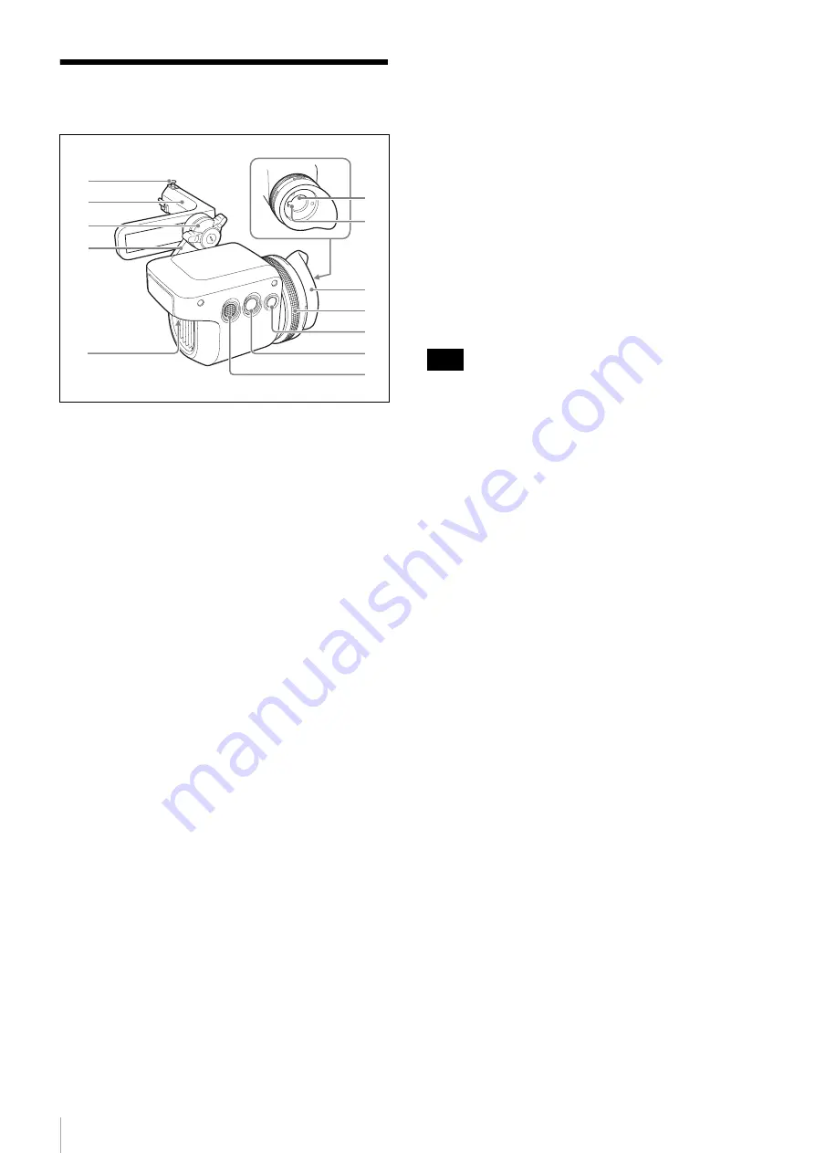
Parts Identification
a
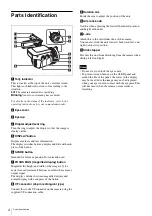
Tally indicator
This is located at the top of the unit’s internal screen.
This lights or blinks red or turns off according to the
situation.
Lit:
The camera/camcorder is recording.
Blinking:
An error or warning has occurred.
For details on the status of the indicator, refer to the
operating instructions for your camera/camcorder.
b
Eye sensor
c
Eyecup
d
Diopter adjustment ring
Turn the ring to adjust the diopter so that the image is
clearly visible.
e
DISPLAY button
Displays markers and text information.
The display switches between display and hide with each
press of the button.
f
SPARE button
Intended for future expansion. Not currently used.
g
FOCUS MAG (magnified display) button
Magnifies the height and width of the image (x2) for
easier focus adjustment. This does not affect the camera’s
output signal.
The display switches between magnified display and
normal display with each press of the button.
h
VF connector (26-pin rectangular type)
Connect this to the VF connector on the camera using the
supplied VF connection cable.
i
Rotation arm
Rotate the arm to adjust the position of the unit.
j
Arm lock knob
Use this when adjusting the forward/backward position
and height of the unit.
k
L-arm
Attach this to the viewfinder shoe of the camera.
You can also slide the unit forward, backward, left, and
right to adjust its position.
l
Slide stopper
Prevents this unit from detaching from the camera when
sliding it left and right.
• Do not cover or block the eye sensor.
• To prevent screen burn-in on the OLED panel and
extend the life of the panel, the colors in the display
may be inverted or the image may not be displayed
when your eye is not in contact with the eyepiece. This
will not occur when the camera or camcorder is
recording.
1
2
5
6
3
4
7
8
9
0
qa
qs
Notes
Содержание DVF-EL100
Страница 9: ...Sony Corporation ...


