background image

1-2

DSC-W55_L2

1-3. METHOD FOR COPYING OR ERASING THE DATA IN INTERNAL MEMORY

The data can be copied/erased by the operations on the Setup screen. (When erasing the data, execute formatting the internal memory.)

Note 1:

When replacing the SY-176 board, erase the data in internal memory of the board before replacement.

Note 2:

When replacing the SY-176 board, execute formatting and initialize the internal memory after replacement.

Method for Copying the Data in Internal Memory

Method for Formatting the Internal Memory

Copies all images in the internal memory to a “Memory Stick Duo”.

1

Insert a “Memory Stick Duo” having 64 MB or larger capacity.

2

Select [OK] with 

v

 on the control button, then press 

z

.

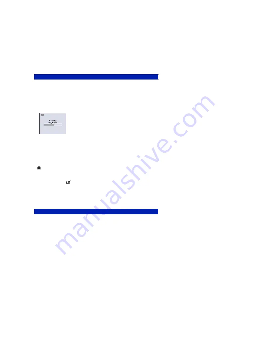
The message “All data in internal memory will be copied Ready?” appears.

3

Select [OK] with 

v

, then press 

z

.

Copying starts. 

To cancel the copying

Select [Cancel] in step 

2

 or 

3

, then press 

z

.

• Use a fully charged battery pack. If you attempt to copy image files using a battery pack with little 

remaining charge, the battery pack may run out, causing copying to fail or possibly corrupting the data.

• You cannot copy individual images.
• The original images in the internal memory are retained even after copying. To delete the contents of the 

internal memory, remove the “Memory Stick Duo” after copying, then execute the [Format] command in 

 (Internal Memory Tool) (page 54).

• When you copy the data in the internal Memory to the “Memory Stick Duo”, all the data will be copied. 

You cannot choose a specific folder on the “Memory Stick Duo” as the destination for the data to be 
copied.

• Even if you copy data, a 

 (Print order) mark is not copied.

Copy

This item appears only when a “Memory Stick Duo” is inserted in the camera. 

Formats the “Memory Stick Duo”. A commercially available “Memory Stick Duo” is already 
formatted, and can be used immediately.

• Note that formatting irrevocably erases all data on a “Memory Stick Duo”, including even protected 

images.

1

Select [OK] with 

v

 on the control button, then press 

z

.

The message “All data in Memory Stick will be erased Ready?” appears.

2

Select [OK] with 

v

, then press 

z

.

The format is complete.

To cancel the formatting

Select [Cancel] in step 

1

 or 

2

, then press 

z

.

Format

Содержание CYBER-SHOT DSC-W55

Страница 1: ...0800 1 2007 09 Published by Kohda TEC The components identified by mark 0 or dotted line with mark 0 are critical for safety Replace only with part num ber specified Les composants identifiés par une marque 0 sont critiques pour la sécurité Ne les remplacer que par une pièce portant le numéro spécifié Precaution on Replacing the SY 176 Board Ver 1 4 2007 09 9 852 160 33 DSC W55 US Model Canadian M...

Страница 2: ...SB 2 0 compliant LCD screen LCD panel 6 2 cm 2 5 type TFT drive Total number of dots 115 200 480 240 dots Power general Power Rechargeable battery pack NP BG1 3 6 V AC LS5K AC Adaptor not supplied 4 2 V Power consumption during shooting with the LCD screen on 1 0 W Operating temperature 0 to 40 C 32 to 104 F Storage temperature 20 to 60 C 4 to 140 F Dimensions 88 9 57 1 22 9 mm 3 1 2 2 1 4 29 32 i...

Страница 3: ...oard Repairing Keep the temperature of the soldering iron around 270 C during repairing Do not touch the soldering iron on the same conductor of the circuit board within 3 times Be careful not to apply force on the conductor when soldering or unsoldering Unleaded solder Boards requiring use of unleaded solder are printed with the lead free mark LF indicating the solder contains no lead Caution Som...

Страница 4: ...sassembly 2 2 2 2 Exchange Method of Barrier Assy 2 6 2 3 Exchange Method of Zoom Motor Unit 2 9 3 BLOCK DIAGRAMS 3 1 Overall Block Diagram 1 2 3 1 3 2 Overall Block Diagram 2 2 3 2 3 3 Power Block Diagram 3 3 4 PRINTED WIRING BOARDS AND SCHEMATIC DIAGRAMS 4 1 Frame Schematic Diagram 4 1 4 2 Schematic Diagrams 4 3 4 3 Printed Wiring Boards 4 16 4 4 Mounted Parts Location 4 25 5 REPAIR PARTS LIST 5...

Страница 5: ...he focus and zoom initialization Checking of flash unit or replacement of flash unit Note Abnormality when flash is being charged Note After repair be sure to perform 1 2 PROCESS AFTER FIXING FLASH ERROR 1 2 PROCESS AFTER FIXING FLASH ERROR When FLASH error Self diagnosis Code E 91 occurs to prevent any abnormal situation caused by high voltage setting of the flash is changed automatically to disa...

Страница 6: ...remaining charge the battery pack may run out causing copying to fail or possibly corrupting the data You cannot copy individual images The original images in the internal memory are retained even after copying To delete the contents of the internal memory remove the Memory Stick Duo after copying then execute the Format command in Internal Memory Tool page 54 When you copy the data in the interna...

Страница 7: ...ordingly change the following data so as to set same initial language as that of the set distributing in each region Initial language Language displayed at the next starting if the setting of Setup menu was reset It is different from the language setting selectable with the menu Initial Language Data Page Address Data Language GP2 GP3 GP4 00 English z z z 04 Spanish z z z 4F 8C 06 Portuguese z z 0...

Страница 8: ... C901 The charging capacitor C901 of the ST 133 board is charged up to the maximum 300 V potential There is a danger of electric shock by this high voltage when the capacitor is handled by hand The electric shock is caused by the charged voltage which is kept without discharging when the main power of the unit is simply turned off Therefore the remaining voltage must be discharged as described bel...

Страница 9: ...D VIEW HARDWARE LIST 1 10 2 Cabinet Rear Block Assy 1 Cabinet Front Block Assy 1 1 20 1 4 20 1 7 20 1 2 Claw 1 8 Claw 1 9 Claw 1 3 2 1 20 2 2 Claw 1 6 20 1 5 Refer to page 2 1 Discharging of the ST 133 board s charging capacitor C901 when discharging the capacitor HELP ...

Страница 10: ...2 3 DSC W55_L2 2 1 2 LCD BLOCK EXPLODED VIEW HARDWARE LIST 3 1 5 3 2 3 Cabinet Upper Block Assy 2 3 2 1 Claw 2 SW 498 Board 1 LCD Block 1 1 Claw 1 3 2 2 1 2 SW 498 HELP ...

Страница 11: ...Claw ST 133 ST 134 Note 1 When you exchange barrier assy and ornamental ring A be sure to follow the procedure carried on 2 2 Exchange Method of Barrier Assembly 2 6 page Note 2 When you exchange zoom motor unit be sure to follow the procedure carried on 2 3 Exchange Method of Zoom Motor Unit 2 9 page HELP 2 4 19 2 1 2 5 CD 604 ...

Страница 12: ... Block 3 4 20 3 6 3 5 Refer to fig 2 1 1 when install BT terminal board service in BT holder block Note 1 Precaution 1 4 when exchanging BT terminal board service Fig 2 1 2 is soldering position about BT terminal board service 1 Install to BT holder block 2 Break the notch fig 2 1 1 RED BLACK WHITE 2 1 RED WHITE BLACK SY 176 BOARD SIDE A soldering three positions fig2 1 2 SY 176 MC 181 HELP ...

Страница 13: ...cled portions 1 2 with the soldering iron Heating temperature is about 300ºC Beware of a burn since the entire Ornamental Ring becomes hot As the adhesive force of Ornamental Ring A is considerably large the forced peeling will damage the group 1 frame Insert the tip of tweezers etc into a notch of the group 1 frame and prize the ring Take extreme care so as not to damage the coated surface of the...

Страница 14: ...ed it must be returned to the home position In returning the ring adjust the location of a projection to the lens direction This is an important part to prevent the dust and light from coming in After removing the Barrier Assy take extreme care not to drop dust or foreign substances in the lens barrel 2 2 3 INSTALL NEW BARRIER ASSY 1 Install new Barrier Assy 2 Tighten two screws Tightening torque ...

Страница 15: ... Ornamental Ring A so that the Ornamental Ring A does not float up until the adhesive hardens Note Be careful not to give a shock After the weight was put no gap must be present in full circumference between Ornamental Ring A and group 1 frame A gap if present causes the crackle sound NG The weight must push in the Ornamental Ring A only If the weight is put on the mold part of the Barrier Assy th...

Страница 16: ...2 3 1 REMOVE OLD ZOOM MOTOR UNIT 1 Remove two screws Discard the removed screws 2 Remove the Zoom Motor Unit 3 Remove the Lens Flexible Board Discard the removed Zoom Motor Unit 2 3 2 INSTALL NEW ZOOM MOTOR UNIT 1 Install the Lens Flexible Board in new Zoom Motor Unit 2 Install new Zoom Motor Unit in the Lens Block 3 Tighten two screws Tightening torque 0 7 kgf 1 2 3 3 1 1 1 2 1 1 3 3 3 2 ...

Страница 17: ...HELP DSC W55_L2 HELP Sheet attachment positions and procedures of processing the flexible boards harnesses are shown CD radiation cushion LCD frame 240 Aluminum Sheet CCD Block Assy Putting Standard ...

Страница 18: ...HELP DSC W55_L2 Fuse Rating Label Cabinet Front Assy space 2mm or less Tripod Screw Tripod Screw Gasket Gasket 230 LCD Flame 240 LCD Flame 240 space 0 5mm Max ...

Страница 19: ... Holder Assy 240 Moare Sheet 240 LCD Frame 240 Note Affix so that align the shape of LCD frame 240 to the moare sheet 240 Affix the moare sheet 240 and the LCD frame 240 firmly so that moare sheet 240 should never float ...

Страница 20: ...DSC W55_L2 Link Link 3 BLOCK DIAGRAMS OVERALL BLOCK DIAGRAM 2 2 OVERALL BLOCK DIAGRAM 1 2 POWER BLOCK DIAGRAM ...

Страница 21: ...101 1 2 IC101_AUIN K26 L26 Y26 H26 U23 XCS_AUDIO BL_L BL_H OVERALL 2 2 PAGE 3 2 1 OVERALL 2 2 PAGE 3 2 3 LCD_HD LCD_VD LCD_CK LCD_D1 LCD_D7 IC202 256M SDRAM 64M SUPER AND 4 6 M7 DSP_QCLKE DSP_QCLKE DSP_QCLK DSP_QCLK N7 A18 A17 XCPU_CSO AE6 DSP_AQ0 DSP_AQ11 DSP_DQ0 DSP_DQ31 DSP_DQM0 DSP_DQM3 DSP_QBA0 DSP_QBA1 CPU_A20 CPU_A21 CPU_D00 CPU_D15 C5 C8 D5 D8 E4 E5 E8 E9 F3 F9 G2 G5 G9 G10 H2 H3 H4 H8 H9 ...

Страница 22: ... D004 D001 CN003 2 2 CN705 2 2 2 3 1 XSTRB_LED XSTRB_LED XSHUTTER_SW POWER S002 S001 S009 S010 MODE DIAL S005 S006 BH001 BATTERY TERMINAL EVER_SRAM S X101 12MHz D23 E4 AA23 W23 H25 U25 AB25 AA26 V25 F22 E22 F9 OVERALL 1 2 PAGE 3 1 3 OVERALL 1 2 PAGE 3 1 1 BL_L C7 D7 XPWR_OFF XCS_DD A6 T25 K25 MS_PWR_ON D3 B10 C9 E9 A4 A7 V1 A6 BL_H N21 P23 FUNCTION KEY ROTARY SWITCH D702 ACCESS D002 FLASH CHARGING...

Страница 23: ...MS_PWR_ON MS_PWR_ON D3 B7 K25 BATT_SENS UNREGMON CE D4 IC101 IC102 CAMERA DSP CPU LENS CONTROL MODE CONTROL FRONT CONTROL 2 6 2 6 AA5 AB5 Y5 A13 B13 D25 D26 C6 C5 B6 XPWROFF SCLK SI SO L007 ST_UNREG ST_UNREG L102 L601 L101 AUDIO AMP 5 6 VIDEO AMP 5 6 IC603 D002 POWER D001 AE AF LOCK SELF TIMER D002 FLASH CHARGING RECORD IC602 D_3 2V D_3 2V D_3 2V A_3 2V A_3 2V AU_3 0V AU_3 0V D_1 2V D_1 2V D_3 2V ...

Страница 24: ...NNECTOR 39 1 1 1 23 14 LEVEL3 SY 176 BOARD SIDE B LEVEL3 SY 176 BOARD SIDE A 28 29 1 10 12 11 CN702 CN901 2 1 30 31 2 38 1 39 2 22 1 1 23 23 1 14 1 2 22 23 CN401 CN301 CN704 CN705 CD 604 FLEXIBLE BOARD ST 134 FLEXIBLE BOARD ST 133 BOARD SIDE B SW 498 BOARD SIDE A SW 498 BOARD SIDE B 1 2 13 14 CN001 3 1 1 25 2 26 27 28 29 1 CN003 14 1 D901 LCD BACKLIGHT IC001 Not supplied IC002 Not supplied 4 1 FRA...

Страница 25: ...ATIC DIAGRAMS COMMON NOTE FOR SCHEMATIC DIAGRAMS ST 134 FLEXIBLE BOARD RL 074 FLEXIBLE BOARD CONTROL SWITCH MC 181 FLEXIBLE BOARD MULTI CONNECTOR CD 604 FLEXIBLE BOARD CCD IMAGER ST 133 BOARD FLASH DRIVE SW 498 BOARD CONTROL SWITCH ...

Страница 26: ...itions voltage and waveform Voltages and waveforms are measured between the measurement points and ground when camera shoots color bar chart of pattern box They are reference values and reference waveforms VOM of DC 10 MΩ input impedance is used Voltage values change depending upon input impedance of VOM used Kinds of capacitor Case size External dimensions mm Yellow A A B B A B Fig a Video output...

Страница 27: ... NC LND021 GND LND032 V3A LND035 V1 LND031 VHLD C003 0 1u LND003 H2B CL001 R009 100k C008 0 01u IC002 ICX629EQP 13 1 V1 2 VST 3 V2 4 N C 7 V3B 8 V4 9 V5A 10 V5B 11 V6 V7 12 N C 13 V8 14 V9 15 V10 16 CCD OUT 17 VH 18 RG 19 N C 20 H1B 21 H2B 22 23 RSS3 24 GND 25 WGND 26 SUB 27 CSUB 28 N C N C 29 VL 30 H1A 31 H2A 32 5 VHLD 6 V3A Note CD 604 flexible complete board IC001 and IC002 are not supplied but...

Страница 28: ...DSC W55_L2 Schematic diagrams of the SY 176 board are not shown Pages from 4 6 to 4 11 are not shown ...

Страница 29: ...SH DRIVE CHARGE CONTROL FLASH CONTROL 10 2 11 4 3 D B 7 8 F 9 12 C E 5 6 CHARGING CAPACITOR FLASH DRIVE FLASH UNIT 13 14 IC001 ST 133 BOARD Note MIC901 is not supplied but this is included in ST 134 flexible complete board LND043 LND008 LND039 LND007 LND010 LND036 LND045 LND016 LND017 LND003 LND006 LND048 LND047 LND009 LND001 LND031 LND034 LND021 LND014 LND044 LND015 LND042 LND038 LND041 LND013 LN...

Страница 30: ...13 14 18 SW 498 BOARD R002 XX Note RL 074 flexible complete board and S003 shutter are not supplied but they are included in cabinet upper 240 block assy C C D002 CL 196SYG CD T D003 MAZW068H0LS0 3 2 1 D001 MAZW068H0LS0 3 2 1 LND014 MODE_DIAL0 LND009 XSTRB_LED LND036 BL_L LND037 BL_H LND017 XAE_LOCK_SW LND005 KEY_AD1 LND018 XSHUTTER_SW LND012 VL_3V LND013 N C LND003 XPOWER_ON LND016 KEY_AD2 LND002...

Страница 31: ...V_GND BATT_XEXT ACV_GND XAV_JACK_IN V_OUT USB_DP ACV_UNREG KEY_A DA A_OUT_L USB_GND XCHG_ON A_GND USB_DM XAV_JACK_IN USB_GND USB_DP USB_VBUS USB_GND V_GND V_LINE_OUT AU_LINE_OUT ACV_GND NC ACV_GND ACV_UNREG ACV_UNREG ACV_GND N C ACV_UNREG ACV_UNREG ACV_GND N C ACV_UNREG ACV_UNREG ACV_GND ACV_GND ACV_GND ACV_UNREG BATT XEXT N C XX MARK NO MOUNT SY 176 MULTI CONNECTOR of LEVEL3 5 6 CN702 PAGE 4 10 2...

Страница 32: ... Link Link 4 3 PRINTED WIRING BOARDS MOUNTED PARTS LOCATION COMMON NOTE FOR PRINTED WIRING BOARDS CD 604 FLEXIBLE BOARD ST 134 FLEXIBLE BOARD ST 133 BOARD RL 074 FLEXIBLE BOARD SW 498 BOARD MC 181 FLEXIBLE BOARD ...

Страница 33: ...r side The other layers patterns are not indicated Through hole is omitted There are a few cases that the part printed on diagram isn t mounted in this model C panel designation THIS NOTE IS COMMON FOR PRINTED WIRING BOARDS 2 1 3 2 1 3 2 1 3 3 4 5 2 1 1 2 3 6 5 4 E B C 3 1 5 2 4 6 1 2 3 6 5 4 3 1 5 2 4 6 1 2 3 5 4 4 3 1 2 3 1 2 4 5 5 3 4 1 2 1 4 2 3 4 6 2 5 3 1 1 2 4 3 1 4 2 3 Chip parts Transisto...

Страница 34: ...08 IC002 CL001 CL002 CL003 CL004 CL005 CL006 R001 R002 R004 R007 R008 R009 IC001 LND001 LND002 LND003 LND004 LND005 LND006 LND007 LND008 LND009 LND010 LND011 LND012 LND013 LND014 LND015 LND016 LND017 LND018 LND019 LND020 LND021 LND022 LND023 LND024 LND025 LND026 LND027 LND028 LND029 LND030 LND031 LND032 LND033 LND034 LND035 LND036 LND037 LND038 LND039 08 1 39 CD 604 FLEXIBLE BOARD 1 867 705 12 Not...

Страница 35: ...DSC W55_L2 Printed wiring boards of the SY 176 board are not shown Page 4 18 is not shown ...

Страница 36: ...5 LND046 LND047 LND048 Note MIC901 is not supplied but this is included in ST 134 flexible complete board ST 133 ST 134 ST 133 4 layers ST 134 2 layers Uses unleaded solder ST 133 BOARD SIDE A ST 133 BOARD SIDE B P P C002 C003 D003 T001 L001 1 3 4 5 2 08 12 1 867 701 D003 SELF TIMER AF ILLUMINATOR 1 6 4 3 ST 133 EP GW B R008 R007 D004 R006 C008 R005 R004 R003 Q001 LND004 LND003 LND002 LND001 IC001...

Страница 37: ... SELF TIMER D002 FLASH CHARGING RECORD 2 1 3 4 1 4 4 5 6 7 8 10 9 11 12 13 14 1 3 2 1 2 3 1 2 4 3 1 2 4 3 1 2 4 3 1 2 4 3 4 3 1 2 4 3 1 2 4 3 1 2 LITHIUM RECHARGEABLE BATTERY BT001 3 1 2 4 3 A B C D 1 2 3 Note S010 is not supplied but this is included in SW 498 complete board LND004 CN003 14 1 LND003 A B C D 1 2 3 08 11 1 871 905 SW 498 SW 498 2 layers Uses unleaded solder SW 498 BOARD SIDE A SW 4...

Страница 38: ... flexible complete board and S003 shutter are not supplied but they are included in cabnet upper 240 block assy RL 074 MC 181 RL 074 2 layers MC 181 2 layers Uses unleaded solder RL 074 FLEXIBLE BOARD 08 MULTI CONNECTOR 1 871 907 11 LND040 28 26 CN001 FB002 FB001 LF001 25 1 27 2 LND001 LND003 LND005 LND007 LND009 LND011 LND013 LND015 LND017 LND019 LND021 LND023 LND025 LND027 LND029 LND002 LND004 L...

Страница 39: ...DSC W55_L2 Mounted parts location of the SY 176 board are not shown Page 4 24 is not shown ...

Страница 40: ... MOUNTED PARTS LOCATION BT001 B3 C001 C3 CN003 A3 D001 A1 D002 A1 D003 B3 D004 C3 D005 B3 LND001 A2 LND002 A2 LND003 A3 LND004 B3 R001 D3 R002 C3 R003 C2 R004 B2 R005 B2 R006 C2 R007 A2 R008 A2 R009 A3 R010 A3 R011 A3 R012 A3 R013 A3 R014 A2 S001 D3 S002 B2 S003 A1 S004 C3 S005 D2 S006 C3 S007 C2 S008 C2 S009 C3 S010 A3 ...

Страница 41: ...WS ACCESSORIES ACCESSORIES NOTE Characters A to Z of the electrical parts list indicate location of exploded views in which the desired part is shown A B C CABINET BLOCK LENS BLOCK LCD BLOCK D BT HOLDER BLOCK MC 181 FLEXIBLE BOARD CD 604 FLEXIBLE BOARD ST 133 BOARD RL 074 FLEXIBLE BOARD ST 134 FLEXIBLE BOARD SW 498 BOARD D C C B C B ...

Страница 42: ...omponents used on the set CAPACITORS uF µF COILS uH µH RESISTORS All resistors are in ohms METAL metal film resistor METAL OXIDE Metal Oxide film resistor F nonflammable SEMICONDUCTORS In each case u µ for example uA µA uPA µPA uPB µPB µPC µPC uPD µPD Abbreviation AR Argentine model AUS Australian model BR Brazilian model CH Chinese model CND Canadian model EE East European model HK Hong Kong mode...

Страница 43: ...DE 3 3 093 837 01 CABINET 240 LE SIDE 4 X 2176 554 1 CABINET REAR ASSY 240 SILVER 4 X 2176 617 1 CABINET REAR ASSY 240 BLACK 4 X 2176 618 1 CABINET REAR ASSY 240 BLUE 4 X 2176 619 1 CABINET REAR ASSY 240 PINK 5 3 093 831 01 SHEET 240 WINDOW ADHESIVE 6 3 093 842 01 WINDOW 240 LCD 7 3 093 834 01 LID PLATE DC 8 3 093 810 01 LABEL FUSE RATING 9 3 100 146 01 SPACER 240 MOARE 20 2 635 591 31 SCREW M1 4 ...

Страница 44: ...46 01 SPACER 240 MOARE 58 3 941 343 21 TAPE A 0BT001 1 756 711 11 LITHIUM RECHARGEABLE BATTERY LCD901 8 753 282 44 ACX358AKQ 3 5 3 080 204 01 SCREW TAPPING P2 Black DISASSEMBLY HARDWARE LIST 5 1 2 LCD BLOCK CAUTION Danger of explosion if battery is incorrectly replaced Replace only with the same or equivalent type Refer to page 5 1 for mark 0 5 LCD901 Lens Block See page 5 4 SW 498 53 including RL...

Страница 45: ...50 01 RING A ORNAMENTAL Note 3 108 2 673 652 01 BARRIER ASSY Note 3 109 2 673 651 01 TAPPING SCREW B1 2X4 Note 3 110 2 673 649 01 BT2 P1 4X3 B3C Note 4 111 3 100 147 01 SHEET 240CD ALUMINUM 112 3 197 877 01 SHEET OVF LCD REINFROCEMENT 113 3 093 841 01 GUARD 240 ST 0 C901 1 112 819 11 ELECT 97uF 315V M901 2 673 648 01 ZOOM MOTOR UNIT Note 4 SP901 1 826 614 11 LOUDSPEAKER 1 0CM 19 3 086 156 21 SCREW...

Страница 46: ...ING 240 BT LOCK 159 2 666 429 01 CUSHION CD RADIATION 160 3 093 839 01 FRAME 240 LCD 161 A 1248 934 A BT TERMINAL BOARD SERVICE Note 2 162 3 093 800 01 GASKET 230 BH001 Not supplied HOLDER 240 BT Note 3 CN001 Not supplied CONNECTOR MULTIPLE SOCKET Note 1 5 3 080 204 01 SCREW TAPPING P2 Black 20 2 635 591 31 SCREW M1 4 NEW TRUSTAR P2 Silver HARDWARE LIST DISASSEMBLY 5 1 4 BT HOLDER BLOCK Refer to t...

Страница 47: ... 1005 LINE FILTER LF001 1 457 223 11 COMMON MODE CHOKE COIL A 1246 250 A CABINET UPPER 240 BLOCK ASSY Not supplied RL 074 FLEXIBLE BOARD COMPLETE RL 074 flexible complete board and S003 shutter are not supplied but they are included in cabinet upper 240 block assy DIODE D001 6 500 776 01 DIODE MAZW068H0LS0 D002 6 500 594 01 DIODE CL 196SYG CD T POWER D003 6 500 776 01 DIODE MAZW068H0LS0 RESISTOR R...

Страница 48: ...S CHIP 2 2K 5 1 16W R002 1 218 957 11 RES CHIP 2 2K 5 1 16W R003 1 218 957 11 RES CHIP 2 2K 5 1 16W R004 1 218 957 11 RES CHIP 2 2K 5 1 16W R005 1 218 957 11 RES CHIP 2 2K 5 1 16W R006 1 218 959 11 RES CHIP 3 3K 5 1 16W R007 1 218 959 11 RES CHIP 3 3K 5 1 16W R008 1 218 959 11 RES CHIP 3 3K 5 1 16W R009 1 218 957 11 RES CHIP 2 2K 5 1 16W R010 1 218 957 11 RES CHIP 2 2K 5 1 16W R011 1 218 957 11 RE...

Страница 49: ...CH ITALIAN CND AEP 2 319 003 31 SPANISH PORTUGUESE AEP E JE AR 2 319 003 41 GERMAN DUTCH AEP 2 319 003 51 TRADITIONAL CHINESE SIMPLIFIED CHINESE E HK JE CH 2 319 003 61 RUSSIAN AEP 2 319 003 71 ARABIC PERSIAN E 2 319 003 81 KOREAN JE 2 319 003 91 POLISH CZECH AEP 2 319 005 11 HUNGARIAN SLOVAK AEP 2 319 005 21 SWEDISH FINISH AEP 2 319 005 31 NORWEGIAN DANISH AEP 2 319 005 52 TURKISH GREEK AEP 2 319...

Страница 50: ... Tapping Black 3 080 204 21 1 7 9 M1 7 X 5 0 Tapping Silver 3 078 890 21 5 0 1 7 14 M1 7 X 2 5 Silver 2 599 475 11 13 M1 7 X 2 5 Tapping Silver 3 085 397 01 2 5 1 7 11 M1 7 X 4 0 Tapping Silver 3 078 890 11 8 M1 7 X 3 5 Tapping Silver 3 078 890 01 3 5 1 7 4 0 1 7 5 0 2 5 17 M1 7 X 1 5 Silver 2 586 389 01 2 5 1 7 15 M1 4 X 1 5 Silver 3 062 214 01 1 5 1 4 1 4 16 M1 4 X 2 5 Silver 2 586 337 01 1 5 3 ...

Страница 51: ...hinese Model Korea Model Argentine Model Brazilian Model Tourist Model Ver 1 3 2007 07 SUPPLEMENT 1 File this supplement with the service manual previously issued DI07 033 ST 133 Board Modification Suffix 12 to 13 2007G0800 1 2007 07 Published by Kohda TEC 9 852 160 82 Suffix No of ST 133 Board has been changed from qx to qc DSC W55 ...

Страница 52: ...SW 3 VCC 4 F_ON 5 N C 6 I_PEAK 7 G_IGBT 8 N C XFULL 9 CHG 10 PGND 11 PGND 12 N C 13 N C 14 VBATT 15 N C 16 HGND 17 C004 1u T001 4 1 2 3 5 D002 MA2YF8000LS0 C002 10V C003 4 7u 4 7u 10V D004 RB520S 40TE61 C008 220p R006 10k R008 10k CHARGE CONTROL FLASH CONTROL IC001 XX C010 4 7u C009 Suffix 12 Page Suffix 13 4 12 ST 133 Board Location B 7 to E 11 ST 133 Board Location B 7 to E 11 The components ide...

Страница 53: ...002 C004 17 9 12 1 13 8 16 5 4 C004 C008 D002 D004 IC001 R006 R008 C009 5 16 A K 8 13 1 4 12 9 17 5 2 ELECTRICAL PARTS LIST Page Suffix 12 Suffix 13 5 6 C009 1 112 746 11 CERAMIC CHIP 4 7uF 10 6 3V Ref No Part No Description CAPACITOR Ref No Part No Description CAPACITOR ST 133 Board ST 133 Board Points Changed portion Points Added portion Points Added portion ...

Страница 54: ...anged from qx to qc About suffix No qx and qc there are no change of schematic diagram and printed wiring board DSC W55 Note Please refer to Ver 1 4 of SERVICE MANUAL 9 852 160 33 for the revision of accessories CD 604 Flexible Board Modification Suffix 12 to 13 RL 074 Flexible Board and MC 181 Flexible Board Modification Suffix 11 to 21 Change of Schematic Diagrams Change of Electrical Parts List...

Страница 55: ...REG_GND LND023 BL_H LND038 STATIC_GND LND022 NC LND021 BL_L R001 2200 S0 1 3 S0 4 1 S005 2 1 3 4 1 3 15 16 17 18 19 20 21 22 23 PO W ZOOM SHUT RL 074 Flexible Board ST 133 Flexible Board RL 074 Flexible Board ST 133 Flexible Board 5 6 D001 6 500 776 01 DIODE MAZW068H0LS0 D003 6 500 776 01 DIODE MAZW068H0LS0 Points deleted portion Points changed portion Page 5 2 ELECTRICAL PARTS LIST 5 REPAIR PARTS...

Страница 56: ... 998 61 1 4 4 0 29 M1 4 X 2 5 Black 2 662 396 01 31 M3 0 X 4 0 Silver 2 102 434 01 2 5 1 4 30 M1 2 X 4 0 Tapping White 3 086 156 11 3 5 1 2 32 M2 0 X 4 5 Tapping Silver 2 102 498 01 33 M3 0 X 6 0 Silver 3 077 331 21 35 M4 0 X 6 0 Tapping Silver 3 975 291 02 34 M3 0 X 8 0 Black 3 077 331 41 36 M3 0 X 6 0 Silver 4 886 821 11 37 M2 0 X 6 0 Tapping Black 3 080 206 31 38 M3 0 X 20 0 Tapping Silver 7 68...

Страница 57: ...r 3 973 497 91 2 5 1 7 49 M2 0 X 4 0 Black 2 630 005 31 50 M2 0 X 3 0 Red 2 891 494 11 51 M2 0 X 2 5 Silver 3 073 686 01 54 M1 75 X 6 0 Tapping Black 3 318 203 11 53 M2 0 X 5 0 Tapping Black 3 080 206 21 55 M2 0 X 4 0 Silver 2 655 582 11 52 M2 0 X 4 0 Tapping Black 3 080 206 11 56 M2 0 X 3 5 Silver 3 067 187 11 4 0 2 0 3 0 2 0 2 5 2 0 5 0 2 0 4 0 2 0 6 0 1 75 4 0 2 0 3 5 2 0 57 M1 7 X 4 0 Black 7 ...

Страница 58: ...HARDWARE LIST 4 4 61 M3 0 X 10 0 Black 7 682 549 09 10 0 3 0 62 M2 0 X 3 0 Silver 3 080 202 21 3 0 2 0 63 M5 0 X 12 5 Black 3 060 811 21 12 5 5 0 64 M1 7 X 5 0 Tapping Silver 2 666 551 21 5 0 1 7 ...

Страница 59: ...pplied to the Service Manual depending on the date of issue Switching a page To move to the first page click the To move to the last page click the To move to the previous page click the To move to the next page click the Reversing the screens displayed once To reverse the previous screens operation one by one click the To advance the reversed screens operation one by one click the Application to ...

Страница 60: ...he Printed Wiring Boards and Schematic Diagrams Correction of Repair Parts S M Correction Page 3 1 3 2 3 3 4 13 4 19 4 20 4 21 5 2 5 3 5 5 5 6 5 7 5 11 ST 133 Board Modification Suffix 12 to 13 CD 604 Flexible Board Modification Suffix 12 to 13 RL 074 Flexible Board and MC 181 Flexible Board Modification Suffix 11 to 21 Change of Schematic Diagrams Change of Electrical Parts List Revision of Acces...

Отзывы: