background image

In

s

ta

llat
ion
 a

nd 

Conne

c

tio

ns

Installation


54

Installation and Connections

Installation

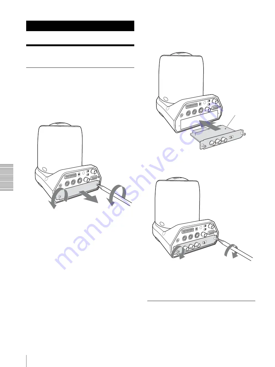
Attaching an Output Card

Attach an Output Card (not supplied) to the card slot on 
the rear of the camera.

1

Loosen the two screws to remove the card slot 
cover.

2

Insert an optional Output Card into the card slot. 
Align both ends of the Output Card with the sliders 
inside the slot, then insert the board securely as far 
as it will go.

3

Tighten the two screws on the Output Card.

To remove the Output Card

Loosen the two screws on the Output Card and pull the 
board out straight and slowly.

Installing the Camera

To install the camera on a desk

Place the camera on a flat surface.

Output Card 
(not supplied)

Содержание BRC-Z330

Страница 1: ...ed in Japan Printed on recycled paper HD Color Video Camera Operating Instructions Before operating the unit please read this manual thoroughly and retain it for future reference BRC Z330 4 149 933 13 1 2009 Sony Corporation ...

Страница 2: ... equipment generates uses and can radiate radio frequency energy and if not installed and used in accordance with the instruction manual may cause harmful interference to radio communications Operation of this equipment in a residential area is likely to cause harmful interference in which case the user will be required to correct the interference at his own expense You are cautioned that any chan...

Страница 3: ...t supplied 27 BRBK SA1 Analog SD Output Card not supplied 28 Adjusting and Setting With Menus About On Screen Menus 29 Main Menu 29 Setting Menus 29 Operation Through Menus 30 Menu Operation Using the Supplied Remote Commander 30 Menu Operation Using the RM BR300 Remote Control Unit 31 EXPOSURE Menu 32 COLOR Menu 33 PICTURE Menu 34 FOCUS Menu 35 PAN TILT ZOOM Menu 36 SYSTEM Menu 37 VIDEO OUT Menu ...

Страница 4: ...ped with VISCA RS 232C Connector 64 Connecting a Device Equipped with VISCA RS 422 Connector 64 Connecting a Video Monitor VTR etc Equipped with Composite Video or S Video Input Connector 65 Connecting a VTR Equipped with HD SDI Input Connectors 66 Connecting the BRU SF10 HD Optical Multiplex Unit 66 Connecting a Sync Signal Generator 67 Appendix List of Messages 69 Troubleshooting 70 Menu Configu...

Страница 5: ...ith a lens cover Ventilation To prevent heat buildup do not block air circulation around the camera Transportation When transporting the camera repack it as originally packed at the factory or in materials equal in quality Cleaning Use a blower to remove dust from the lens or optical filter Use a soft dry cloth to clean the external surfaces of the camera Stubborn stains can be removed using a sof...

Страница 6: ... raised the gain sensitivity This symptom may be improved by turning the camera off and then on again Aliasing When fine patterns stripes or lines are shot they may appear jagged or flicker Focal plane Owing to the characteristics of the pickup elements CMOS image sensors for reading video signals subjects that quickly move across the screen may appear slightly skewed Flicker If recording is made ...

Страница 7: ...nd use them for HD output in the future An analog component signal output connector for HD output a composite signal output connector and an S video signal output connector for SD output standard equipment 1 HD indicates high definition broadcast with 1 080 effective scanning lines 2 SD indicates standard definition broadcast conventional television Built in interface card slot The camera is equip...

Страница 8: ...utral Density filter allows control of amount of light The ND filter can be set to 1 4 or 1 16 using the menu or Remote Commander System Components In order to support multiple system configurations a variety of optional products are available for the BRC Z330 HD Color Video Camera This section introduces these optional products as well as the accessories supplied with the camera Supplied Componen...

Страница 9: ...e Control Unit allows you comfortable pan tilt and zoom operations The Remote Control Unit also allows remote operation of up to seven cameras Supplied accessories AC power adaptor 1 AC power cord 1 RS 232C connecting cable 3 m 1 RS 422 connector plug 2 BRBK SF1 HD Optical Multiplex Card Insert the card into the camera to allow high bit multiplex transfer via optical fiber cable video audio extern...

Страница 10: ...00 m 6 562 feet using the CCFC S200 2 core optical fiber cable Supplied accessories AC adapter 1 power cord 1 DC cable secure connection attachment 1 RS 232C connecting cable 3 m 10 feet 1 RS 422 connector plug 1 CCFC S200 Optical Fiber Cable This is a 2 core single mode optical fiber cable of 2 000 m 6 562 feet long Supplied accessories extension plug 1 Video Switcher commercially available It sw...

Страница 11: ...11 Control cable for connection between the Processor Unit and Control Panel 1 RS 422 connector plug 1 Rack mounting bracket 1 set rack mounting bracket screw 2 DC IN connector retainer 1 For details consult with your Sony dealer ...

Страница 12: ...Remote Commander This system allows you To operate the camera readily from a short distance System configuration Operating a BRC Z330 Camera Using the RM BR300 Remote Control Unit This system allows you To perform pan tilt and zoom operations using the joystick of the Remote Control Unit System configuration BRC Z330 Video signal Signal flow Remote Commander supplied HD video monitor VTR etc HD vi...

Страница 13: ...you To operate up to seven cameras remotely using a single Remote Control Unit To perform pan tilt and zoom operations using the joystick System configuration Video signal Remote control VISCA signal Tally contact signal Signal flow BRC Z330 BRC Z330 BRC Z330 HD video monitor VTR etc Video switcher RM BR300 Remote Control Unit ...

Страница 14: ...al BRBK HSD2 HD SD SDI Output Card or BRBK HD2 HD SDI Output Card in the BRC Z330 which cannot be controlled this way without a BRBK HSD2 HD SDI Output Card or BRBK HD2 HD SDI Output Card installed BRS 200 Remote Camera Operating Switcher does not support mixed input of HD SDI and SD SDI signals For details refer to the Operating Instructions supplied with the BRS 200 BRS 200 REMOTE CAMERA OPERATI...

Страница 15: ...CFC S200 Optical Fiber Cable and turn on the power of the BRU SF10 When the BRBK SF1 HD Optical Multiplex Card is inserted into the BRC Z330 camera the EXT SYNC IN connector VISCA RS 232C IN OUT connectors VISCA RS 422 connector DATA MIX switch and 75 ohm termination switch on the rear of the camera and the BOTTOM switches on the bottom of the camera are disabled Use the connectors and switches on...

Страница 16: ...To transmit the video signal and control signal of the cameras to a distant place using the Optical Fiber Cable System configuration BRC Z330 BRC Z330 BRC Z330 BRBK SF1 HD Optical Multiplex Card BRBK SF1 BRBK SF1 BRU SF10 Optical Multiplex Unit BRU SF10 HD video monitor VTR etc BRU SF10 Video switcher RM BR300 Remote Control Unit CCFC S200 Optical Fiber Cable CCFC S200 CCFC S200 Video signal Remot...

Страница 17: ... operations using the joystick To control the BRC Z330 cameras remotely from a distance up to 2 000 m 6 562 feet by transmitting the video signal and control signal using the Optical Fiber Cable System configuration VISCA controllable camera BRC Z330 BRC Z330 BRBK SF1 BRBK SF1 HD Optical Multiplex Card HD video monitor VTR etc BRU SF10 Video switcher RM BR300 Remote Control Unit CCFC S200 Optical ...

Страница 18: ...ignal and control signal of the camera and the audio signal input to the BRBK SF1 Optical Multiplex Card to a distant place using the Optical Fiber Cable System configuration BRC Z330 Microphone HD video monitor RM BR300 Remote Control Unit CCFC S200 Optical Fiber Cable Video signal Audio line signal Remote control VISCA signal Signal flow Microphone amplifier BRBK SF1 HD Optical Multiplex Card Sp...

Страница 19: ... Connect the supplied AC power adaptor H VISCA RS 422 connector Used for VISCA control For connection to the VISCA RS 422 connector see Using the VISCA RS 422 Connector Plug on page 89 I IR SELECT switch Select the camera number when you operate multiple cameras with the same Remote Commander page 44 J Remote sensor This is the sensor for the supplied Remote Commander This remote sensor does not f...

Страница 20: ...ipod to these holes V BOTTOM switches Used for the output signal format selection RS 232C RS 422 selection baud rate selection remote control signal output on off and camera address setting For details see Setting of the BOTTOM switches on page 20 Setting of the BOTTOM switches 1 Switch 1 59 94 50 signal format selector Set to ON for output in 1080 50i 720 50p signal format OFF for output in 1080 ...

Страница 21: ...B FOCUS buttons Used for focus adjustment Press the AUTO button to adjust the focus automatically To adjust the focus manually press the MANUAL button and adjust it with the FAR and NEAR buttons C DATA SCREEN button Press this button to display the main menu Press it again to turn off the menu If you press the button when a lower level menu is selected the display returns to the next menu one leve...

Страница 22: ... the Operating Instructions supplied with the RM BR300 Front A LOCK button and indicator Press the LOCK button for more than one second and the LOCK indicator lights and the values set by the VALUE R BRIGHT B and FOCUS controls are locked The indicators of the locked controls are turned off The AUTO MANUAL button is also disabled Press the LOCK button for more than one second again to unlock the c...

Страница 23: ...red to the factory preset conditions When multiple cameras are connected hold down this button and press the POWER button to set the camera addresses automatically I PRESET button Hold down this button and press one of the POSITION buttons and the current camera settings are stored in the memory of the camera corresponding to the pressed POSITION button J PANEL LIGHT button Press this button to il...

Страница 24: ...era is in standby mode Off No camera is connected Hold down this button and press CAMERA button 1 to 7 to turn on off the power of the camera corresponding to the pressed button S CAMERA buttons Press one of the buttons to select the camera from among those connected The selected CAMERA button lights in blue T POSITION buttons You can store the various camera settings such as the pan tilt and zoom...

Страница 25: ... Control Unit BRU SF10 HD Optical Multiplex Unit not supplied Front A Power switch Turns on off the power of this unit Turn on the power of the BRC Z330 camera before you turn on this unit B Power indicator Off The unit s power switch is turned off Lit orange The unit is starting up or in sleep mode Lit green The unit is in normal operation C LINK indicator Lit green The optical fiber connection b...

Страница 26: ...c signals input from the EXT SYNC IN connector When a cable is connected to this connector the 75 ohm termination for inputs is automatically opened and signals input to the EXT SYNC IN connector are output from this connector L RGB COMPONENT connector Supplies the images from the camera as YPbPr or RGB signal M VISCA RS 232C IN connector Connect to the RM BR300 Remote Control Unit not supplied Wh...

Страница 27: ...tc it should be connected with a microphone amplifier so that audio signals with an appropriate audio level can be input B Optical connector Performs the optical digital multiplex transmission of video audio external sync and control signals A dustproof cap is attached at the factory BRBK HSD2 HD SD SDI Output Card not supplied A SDI MONITOR OUT connector BNC type Outputs down converted SD SDI sig...

Страница 28: ...nnector BNC type Supplies analog composite signals The aspect ratio can be configured in the SD menu of the camera B S VIDEO connector 4 pin mini DIN Outputs S Video signals You can configure the aspect ratio with the SD menu of the camera C RGB SYNC connector D sub 9 pin Supplies various analog signals such as composite video S video component video and RGB signals The output signal can be select...

Страница 29: ...ard indicator Displays the name of the output card inserted into the card slot of the camera The illustration above shows an example when the BRBK HD2 HD SDI Output Card is inserted Setting Menus The setting menu selected on the main menu is displayed 1 Setting menu The name of the setting menu currently selected is displayed here 2 Cursor Selects a setting item Move the cursor up or down by press...

Страница 30: ...set IR RECEIVE in the SYSTEM menu to OFF To set IR RECEIVE to OFF use the RM BR300 Remote Control Unit or the VISCA command To return to the main menu Press the DATA SCREEN button To return to the normal display When the main menu is displayed press the DATA SCREEN button once If a lower level menu is displayed press it twice P O W E R C A M E R A S E L E C T 1 2 3 A U T O P O S IT IO N H O M E R ...

Страница 31: ...out one second To return to the normal display When the main menu is displayed press the MENU button once If a lower level menu is displayed press it twice When pressing the MENU button hold it pressed for about one second 1 1 9 LOCK MODE VALUE RESET MENU PRESET SHIFT L R DIRECTION PANEL LIGHT BLACK LIGHT PAN TILT RESET ONE PUSH AWB POWER AUTO MANUAL AUTO ONE PUSH AF 2 3 4 5 6 7 2 10 STD REV 3 11 ...

Страница 32: ...lowing For the 1080 59 94i or 720 59 94p signal format 1 10000 1 6000 1 4000 1 3000 1 2000 1 1500 1 1000 1 725 1 500 1 350 1 250 1 180 1 125 1 100 1 90 1 60 For the 1080 50i or 720 50p signal format 1 10000 1 6000 1 3500 1 2500 1 1750 1 1250 1 1000 1 600 1 425 1 300 1 215 1 150 1 120 1 100 1 75 1 50 IRIS Select the iris from among the following CLOSE F16 F15 F14 F12 F11 F10 F9 6 F8 7 F8 0 F7 3 F6 ...

Страница 33: ...DOOR OUTDOOR ONE PUSH MANUAL AUTO1 Adjusts the white balance automatically while leaving natural colors AUTO2 Adjusts the white balance automatically INDOOR The R GAIN and B GAIN values are fixed to those for a color temperature of 3200K OUTDOOR The R GAIN and B GAIN values are fixed to those for a color temperature of 5800K ONE PUSH The white balance adjustment is activated when you zoom in on a ...

Страница 34: ...he adjustable level is in the range of 0 to 15 The larger the setting level the sharper the image outline You can obtain the softest image outline by selecting level 0 COLOR DETAIL Reduces the image enhancer of a specific color OFF COLOR DETAIL does not function CHECK The region of the color specified with PHASE is displayed in white The region is set to STD when CHECK is selected NARROW The regio...

Страница 35: ...onitor screen FOCUS Menu The FOCUS menu is used to select the focus mode MODE focus mode Select the focus adjustment mode AUTO The focus is adjusted automatically MANUAL Adjust the focus manually Use the FAR NEAR buttons on the supplied Remote Commander to adjust the focus Note Set MODE to MANUAL when you shoot a flat subject with low contrast such as a white wall a subject through glass a lateral...

Страница 36: ... the range of the PAN TILT LIMIT setting you cannot store the camera position in the preset memory The PAN TILT LIMIT setting is reset to the factory setting when you change IMG FLIP of the SYSTEM menu RAMP CURVE Select the speed acceleration or reduction mode when the preset operation is recalled MODE1 Speed accelerates or reduces most sharply MODE2 Speed accelerates or reduces moderately MODE3 S...

Страница 37: ...put Card if one is installed in a card slot upside down and to reverse the direction of the camera movement with pan tilt operations PAN REVERSE Set to ON to reverse the horizontal movement of the camera image TILT REVERSE Set to ON to reverse the vertical movement of the camera image When you set IMG FLIP to ON Please restart system appears Turn off the power of the camera and turn it on again No...

Страница 38: ... H PHASE on the menu the message PUSH ENTER BUTTON appears on the screen Press the HOME button on the Remote Commander or the button on the top of the joystick on the Remote Control Unit to make the color bars appear After completing the adjustment press the HOME button on the Remote Commander or the button on the top of the joystick on the Remote Control Unit to make the color bar disappear Note ...

Страница 39: ...elected with the EXPOSURE menu PAGE2 Shows the settings selected with the COLOR menu PAGE3 Shows the settings selected with the PICTURE menu PAGE4 Shows the settings selected with the FOCUS and SYSTEM menus PAGE5 Shows the settings selected with the PAN TILT ZOOM menu PAGE6 Shows the settings selected with the VIDEO OUT menu status of the fan motors the firmware versions of the BRC Z330 the firmwa...

Страница 40: ...nal 16 9 LETTER The image is displayed in 16 9 letterbox 4 3 CROP The image is displayed in 4 3 edge crop 4 3 SQUEEZE The image is displayed in 4 3 squeeze Notes When a BRBK SA1 Analog SD Output Card is installed in the BRC Z330 HD Color Video Camera the IMG SIZE settings in the SD menu and VIDEO OUT menu are linked If you change the IMG SIZE setting in the SD menu the IMG SIZE setting for outputs...

Страница 41: ...isplayed in 4 3 edge crop 4 3 SQUEEZE The image is displayed in 4 3 squeeze Notes When a BRBK HSD2 HD SD SDI Output Card is installed in the BRC Z330 HD Color Video Camera the IMG SIZE settings in the SD SDI menu and VIDEO OUT menu are linked If you change the IMG SIZE setting in the SD SDI menu the IMG SIZE setting for outputs from the VIDEO and S VIDEO connectors on the BRC Z330 HD Color Video C...

Страница 42: ... the STANDBY lamp lights on the camera Notes When you turn off the camera using the Remote Commander the camera tilts downward to protect the lens from dust before entering Standby mode When IMG FLIP is set to ON in the SYSTEM menu however the camera tilts the opposite way so that the lens faces downward when the camera is installed suspended from a ceiling When a BRU SF10 HD Optical Multiplex Uni...

Страница 43: ...xample when you change the direction of the camera while checking the picture on the screen In such a case press the 2 REV button while holding down the L R DIRECTION SET button To reset the setting press the 1 STD button while holding down the L R DIRECTION SET button Note The setting above only changes the signal emitted from the Remote Commander and does not change the setting of the camera its...

Страница 44: ...amera focuses on the subject at the center of the screen automatically To focus the camera on a subject manually After pressing the MANUAL button press either the FAR or the NEAR button to have the camera focus on the subject PAN TILT RESET RM EV100 SLOW FAST ZOOM L R DIRECTION SET T T W W Subject appears farther away Wide angle Subject appears closer Telephoto Zooms in or out slowly SLOW side Zoo...

Страница 45: ...it not supplied to store the settings in POSITION 7 to 16 For details of the camera settings to be preset see Presetting Items on page 77 1 Press the PAN TILT RESET button to reset the pan tilt position 2 Adjust the position zooming focusing and backlighting of the camera pages 43 to 44 3 While holding down the PRESET button press any of the POSITION buttons 1 to 6 in which you want to store the s...

Страница 46: ...wer is turned on the camera starts with the settings stored in POSITION 1 If you want to retain the previous pan and tilt positions etc when the power is turned off and turned on again store those positions in POSITION 1 Storing or canceling the settings in POSITION 1 takes about 2 seconds longer than those of other positions When you are storing or canceling the settings in one POSITION you canno...

Страница 47: ... While holding down the POWER button press the CAMERA button corresponding to the camera whose power you want to turn on off When you turn the power off using the Remote Control Unit the POWER lamp turns off and the STANDBY lamp lights on the camera Note When you turn off the camera using the Remote Commander the camera tilts downward to protect the lens from dust before entering Standby mode When...

Страница 48: ...urn on the power of the camera and the RM BR300 Remote Control Unit The camera will turn on performing the pan tilt reset action automatically 2 Press the CAMERA button corresponding to the camera you want to operate 3 Operate the joystick to pan or tilt the camera While checking the picture on the screen incline the joystick in the desired direction The panning tilting speed changes according to ...

Страница 49: ...in which you inclined the joystick for example when you change the direction of the camera while checking the picture on the screen In such a case press the POSITION 2 REV button while holding down the L R DIRECTION button To reset the setting press the POSITION 1 STD button while holding down the L R DIRECTION button Note The setting above only changes the signal emitted from the RM BR300 Remote ...

Страница 50: ...at the AUTO indicator turns off Then turn the FOCUS control clockwise or counterclockwise to have the camera focus on the subject One push auto focusing during manual focus adjustment Press the ONE PUSH AF button The camera focuses on the subject in the center of the screen automatically Subject appears farther away Wide angle Subject appears closer Telephoto 1 1 9 LOCK MODE VALUE RESET MENU PRESE...

Страница 51: ... 2 Press the ONE PUSH AWB button The white balance is adjusted automatically To adjust the white balance manually 1 Set WHITE BALANCE to MANUAL in the COLOR menu of the camera For setting see COLOR Menu on page 33 2 Press the MODE button so that the R and B indicators on the VALUE R and BRIGHT B controls light White balance adjustment mode 3 Adjust the red gain with the R control and the blue gain...

Страница 52: ...ress the CAMERA button to select the camera whose settings you want to preset 3 Adjust the position zooming focusing and backlighting of the camera See page 48 to 50 MODE setting Function of VALUE control Function of BRIGHT control FULL AUTO Not used Exposure compensation level control SHUTTER Pri Shutter speed control Exposure compensation level control IRIS Pri F number control Exposure compensa...

Страница 53: ... 1 When you are storing or canceling the settings in one POSITION you cannot call up store or cancel the settings in another POSITION Setting the Speed of the Camera Moving to a Preset Position You can select the panning tilting speed when the camera moves to a preset position 1 Press the CAMERA button to select the camera whose speed you want to set 2 Press the POSITION button for which you want ...

Страница 54: ...er 2 Insert an optional Output Card into the card slot Align both ends of the Output Card with the sliders inside the slot then insert the board securely as far as it will go 3 Tighten the two screws on the Output Card To remove the Output Card Loosen the two screws on the Output Card and pull the board out straight and slowly Installing the Camera To install the camera on a desk Place the camera ...

Страница 55: ...tallation The connecting cables cannot be passed through the ceiling bracket A A hole for the wiring is required in the ceiling or shelf etc behind where the camera is to be installed When installing the camera on a ceiling make the required hole for the junction box in the ceiling When installing it on a shelf etc in a high position a hole with a diameter of 70 mm 2 7 8 inches is required for the...

Страница 56: ... other screws may damage the camera 4 Attach the wire rope to the junction box on the ceiling Use an M4 or larger outside diameter screw not supplied to attach the wire rope to the junction box 5 Attach the ceiling bracket B to the junction box on the ceiling Align the holes in the bracket with those in the junction box and use appropriate screws not supplied There are three screw holes along the ...

Страница 57: ...hole in the front of the ceiling bracket A aligned with the f hole on the ceiling bracket B and temporarily attach them by turning the ceiling bracket A with the camera clockwise 8 Secure the ceiling brackets A and B using the supplied three screws 3M3 8 For attaching the wire rope to the bracket use only the supplied screw Using another screw may disable the function of the wire rope 3M4 8 suppli...

Страница 58: ... ceiling example 2 Turn the camera with the bracket counterclockwise to remove Installation on a shelf etc in a high position example 1 Remove the four screws on the bottom of the camera to remove the four feet 2 Attach the ceiling bracket A to the bottom of the camera using the supplied four screws 3M3 8 Position the a hole for screwing on the ceiling bracket A to the front of the camera as illus...

Страница 59: ... the camera is to be installed Use four screws not supplied appropriate for the materials of the shelf etc Align the f hole on the ceiling bracket B in the direction where the front of the camera will be positioned later For attaching the wire rope to the bracket use only the supplied screw Using another screw may disable the function of the wire rope 3M4 8 supplied Wire rope supplied Ceiling brac...

Страница 60: ...he shelf etc where the ceiling bracket B is attached 6 Insert the protrusions on the ceiling bracket A into the spaces prepared in the ceiling bracket B with the a hole in the front of the ceiling bracket A aligned with the f hole on the ceiling bracket B and temporarily attach them by turning the ceiling bracket A with the camera clockwise M4 or larger diameter screw Wire rope supplied Ceiling br...

Страница 61: ...onnectors on the rear of the camera Note Take the proper steps to ensure that the load of the cables connected does not cause problems To remove the camera 1 Remove the three screws used to attach the camera in step 7 of Installation on a shelf etc in a high position example 2 Turn the camera with the bracket counterclockwise to remove 3M3 8 supplied ...

Страница 62: ...switch on the bottom of the Remote Control Unit page 25 are set to RS 232C RGB COMPONENT VISCA RS 422 1 2 3 4 5 6 7 8 9 EXT SYNC IN VIDEO IR SELECT 75 1 2 3 OFF ON DATA MIX OFF ON IN VISCA RS 232C OUT S VIDEO DC IN 12V R AC power adaptor MPA AC1 supplied to AC outlet DC IN 12V AC power cord supplied RGB COMPONENT VISCA RS 422 1 2 3 4 5 6 7 8 9 EXT SYNC IN VIDEO IR SELECT 75 1 2 3 OFF ON DATA MIX O...

Страница 63: ...CA RS 422 connectors check that the BOTTOM switch on the bottom of the camera page 20 and the DIP switch on the bottom of the Remote Control Unit page 25 are set to RS 422 When the connections using the VISCA RS 422 connectors are made the VISCA RS 232C connection is not available Connecting a Monitor etc Equipped with the Analog Component YPbPr Input Connector RGB COMPONENT VISCA RS 422 1 2 3 4 5...

Страница 64: ...e use of the RS 422 connector plugs see page 89 Notes When using the VISCA RS 422 connectors check that the BOTTOM switch on the bottom of the camera page 20 and the DIP switch on the bottom of the Remote Control Unit page 25 are set to RS 422 When the connections using the VISCA RS 422 connectors are made the VISCA RS 232C connection is not available Do not make the VISCA RS 422 connection and th...

Страница 65: ... 2 3 4 5 6 7 8 9 EXT SYNC IN VIDEO IR SELECT 75 1 2 3 OFF ON DATA MIX OFF ON IN VISCA RS 232C OUT S VIDEO DC IN 12V R RM BR300 Remote Control Unit DC IN 12V VISCA RS 422 VISCA RS 422 cable First BRC Z330 DC IN 12V DC IN 12V VISCA RS 422 cable Third to Seventh BRC Z330 DC IN 12V VISCA RS 422 VISCA RS 422 VISCA RS 422 VISCA RS 422 VISCA RS 422 cable VISCA RS 422 Second BRC Z330 RGB COMPONENT VISCA R...

Страница 66: ...cal Multiplex Unit page 26 and the DIP switch on the RGB COMPONENT VISCA RS 422 1 2 3 4 5 6 7 8 9 EXT SYNC IN VIDEO IR SELECT 75 1 2 3 OFF ON DATA MIX OFF ON IN VISCA RS 232C OUT S VIDEO DC IN 12V R BRBK HSD2 HD SDI Output Card DC IN 12V SDI OUTPUT Connecting cable with BNC connectors to HD SDI input HDCAM etc equipped with an HD SDI input connectors RGB COMPONENT VISCA RS 422 1 2 3 4 5 6 7 8 9 EX...

Страница 67: ...To connect two Optical Fiber Cables use the extension plug supplied with the cable Connecting a Sync Signal Generator To connect a single camera BRC Z330 CCFC S200 Keep more than 40 mm 1 5 8 inches radius BRU SF10 CCFC S200 A B Extension plug RGB COMPONENT VISCA RS 422 1 2 3 4 5 6 7 8 9 EXT SYNC IN VIDEO IR SELECT 75 1 2 3 OFF ON DATA MIX OFF ON IN VISCA RS 232C OUT S VIDEO DC IN 12V R 75 ohm term...

Страница 68: ... IN Third to Seventh last BRC Z330 Commercially available T type signal separator HD sync signal generator 75 ohm coaxial cable 75 ohm termination switch OFF 75 ohm termination switch OFF to SYNC OUT RGB COMPONENT VISCA RS 422 1 2 3 4 5 6 7 8 9 EXT SYNC IN VIDEO IR SELECT 75 1 2 3 OFF ON DATA MIX OFF ON IN VISCA RS 232C OUT S VIDEO DC IN 12V R RGB COMPONENT VISCA RS 422 1 2 3 4 5 6 7 8 9 EXT SYNC ...

Страница 69: ... Sony dealer ENTER EXIT This message appears while you adjust H PHASE in the SYSTEM menu To exit from the adjustment press the HOME button on the Remote Commander or the button on the top of the joystick on the Remote Control Unit PUSH ENTER BUTTON This message appears when you move the cursor to H PHASE in the SYSTEM menu To start the H PHASE adjustment press the HOME button on the Remote Command...

Страница 70: ...IVE in the SYSTEM menu is set to OFF Use the RM BR300 Remote Control Unit to open the menu and set IR RECEIVE to ON page 37 The camera is connected to a BRU SF10 HD Optical Multiplex Unit The camera cannot be turned on off using the supplied Remote Commander Instead use the power switch on the BRU SF10 or the POWER button on a RM BR300 connected to the BRU SF10 to turn on off the camera The pictur...

Страница 71: ...The NC No Connection switch is set to ON Set camera address selector switch 9 10 of the BOTTOM switches on the bottom of the camera to OFF page 20 The VISCA control is not available with a computer connected to the camera The computer is not correctly connected to the camera Make sure the connection between the computer and camera is made correctly Check that the VISCA control setting RS 232C or R...

Страница 72: ...5 F14 F12 F11 F10 F9 6 F8 7 F8 0 F7 3 F6 8 F6 2 F5 6 F5 2 F4 8 F4 4 F4 0 F3 7 F3 4 F3 1 F2 8 F2 6 F2 4 F2 2 F2 0 F1 8 F1 7 F1 6 SHUTTER Pri SPEED 1 10000 1 6000 1 4000 1 3000 1 2000 1 1500 1 1000 1 725 1 500 1 350 1 250 1 180 1 125 1 100 1 90 1 60 1080 59 94i 720 59 94p NTSC 1 10000 1 6000 1 3500 1 2500 1 1750 1 1250 1 1000 1 600 1 425 1 300 1 215 1 150 1 120 1 100 1 75 1 50 1080 50i 720 50p PAL I...

Страница 73: ...1 0 1 2 3 4 5 6 7 COLOR MATRIX ON R ENHANCE 10 9 8 7 6 5 4 3 2 1 0 1 2 3 4 5 6 7 8 9 10 G ENHANCE 10 9 8 7 6 5 4 3 2 1 0 1 2 3 4 5 6 7 8 9 10 B ENHANCE 10 9 8 7 6 5 4 3 2 1 0 1 2 3 4 5 6 7 8 9 10 YL ENHANCE 10 9 8 7 6 5 4 3 2 1 0 1 2 3 4 5 6 7 8 9 10 CY ENHANCE 10 9 8 7 6 5 4 3 2 1 0 1 2 3 4 5 6 7 8 9 10 MG ENHANCE 10 9 8 7 6 5 4 3 2 1 0 1 2 3 4 5 6 7 8 9 10 OFF page 33 PICTURE DETAIL 0 1 2 3 4 5 ...

Страница 74: ...G FLIP ON OFF PAN REVERSE ON OFF TILT REVERSE ON OFF DISPLAY INFO ON OFF SYNC MASTER HD SD H PHASE1 0 10 330 page 37 1 Does not appear when a BRU SF10 HD Optical Multiplex Unit is in use VIDEO OUT HD RGB COMPONENT FORMAT YPBPR SYNC TYPE SYNC VD RGB ADD SYNC RGB OFF SYNC TYPE SYNC VD SD VIDEO S VIDEO IMG SIZE 16 9 LETTER 4 3 CROP 4 3 SQUEEZE SETUP1 ON OFF 1 Does not appear when an output signal is ...

Страница 75: ...R GAIN COLOR HUE COLOR MATRIX ENHANCE R G B YL CY MG PAGE 3 DETAIL COLOR DETAIL PHASE GAMMA KNEE POINT FLICKER CANCEL B W COLOR BAR PAGE 4 FOCUS MODE NEAR LIMIT AF ASSIST IR RECEIVE IMG FLIP REVERSE PAN TILT DISPLAY INFO SYNC MASTER H PHASE PAGE 5 PAN TILT LIMIT PAN LEFT RIGHT TILT DOWN UP RAMP CURVE D ZOOM PAGE 6 HD FORMAT RGB SYNC SYNC TYPE SD IMG SIZE SETUP FAN MOTOR BRC VERSION page 39 ...

Страница 76: ...nserted SD SDI IMG SIZE 16 9 LETTER 4 3 CROP 4 3 SQUEEZE page 41 SD D SUB OUTPUT 1 YCbCr RGB ADD SYNC RGB OFF D SUB OUTPUT 2 VBS Y C IMG SIZE 16 9 LETTER 4 3 CROP 4 3 SQUEEZE SETUP1 OFF ON page 40 1 Does not appear when an output signal is 1080 50i or 720 50p format ...

Страница 77: ... a a a a a a a a a a GAIN Pri VAL z a a a a a a a a a a a a a a a EX COMP MODE z a a a a a a a a a a a a a a a EX COMP VAL z a a a a a a a a a a a a a a a BACK LIGHT z a a a a a a a a a a a a a a a SPOT LIGHT z a a a a a a a a a a a a a a a COLOR AE1 z a a a a a a a a a a a a a a a PHASE z a a a a a a a a a a a a a a a ND FILTER z a a a a a a a a a a a a a a a WHITE BALANCE MODE z a a a a a a a a ...

Страница 78: ...a a a DETAIL z a a a a a a a a a a a a a a a COLOR DETAIL1 z a a a a a a a a a a a a a a a PHASE z a a a a a a a a a a a a a a a GAMMA z a a a a a a a a a a a a a a a KNEE POINT z a a a a a a a a a a a a a a a FLICKER CANCEL z a a a a a a a a a a a a a a a B W z a a a a a a a a a a a a a a a COLOR BAR FOCUS MODE z a a a a a a a a a a a a a a a NEAR LIMIT z a a a a a a a a a a a a a a a AF ASSIST z...

Страница 79: ... SDI the IMG SIZE settings for both option cards are linked z Setting items retained in memory when the power is turned off and on again The camera starts with these settings a Setting items retained in memory when the power is turned off and on again f Setting items retained in memory only when the power is turned on Setting items cleared from the memory when the power is turned off and on Menu i...

Страница 80: ...p p 0 3 V tri level sync at 75 ohm termination Pb Pr 350 mVp p 75 ohm terminated HD VD Sync 1 Vp p 75 ohm terminated Tri level Sync 300 mVp p 75 ohm terminated VIDEO BNC type Composite 1 Vp p sync negative at 75 ohm termination S VIDEO mini DIN 4 pin S video output Y 1 Vp p sync negative at 75 ohm termination C Same as chroma level of composite signal at 75 ohm termination External sync input EXT ...

Страница 81: ...to change without notice Note Always verify that the unit is operating properly before use SONY WILL NOT BE LIABLE FOR DAMAGES OF ANY KIND INCLUDING BUT NOT LIMITED TO COMPENSATION OR REIMBURSEMENT ON ACCOUNT OF THE LOSS OF PRESENT OR PROSPECTIVE PROFITS DUE TO FAILURE OF THIS UNIT EITHER DURING THE WARRANTY PERIOD OR AFTER EXPIRATION OF THE WARRANTY OR FOR ANY OTHER REASON WHATSOEVER ...

Страница 82: ... 193 4 7 5 8 11 7 16 1 1 1 16 113 4 1 2 14 9 16 93 3 3 4 19 3 4 131 5 1 4 88 3 1 2 152 8 6 1 8 ø5 Depth 5 7 32 1 4 Tripod screw hole Depth 7 5 5 16 83 5 3 3 8 46 1 13 16 120 140 60 40 ø121 2 ø107 3 ø88 9 ø83 5 4 ø4 5 hole Slot widths 4 5 3 16 Unit mm inches Front Bottom Side Top Ceiling Bracket B Top ...

Страница 83: ...IRECTION PANEL LIGHT BLACK LIGHT PAN TILT RESET ONE PUSH AWB POWER AUTO MANUAL AUTO ONE PUSH AF 2 3 4 5 6 7 2 10 STD REV 3 11 4 POSITION CAMERA 12 5 13 6 14 7 15 8 16 R BRIGHT B FOCUS NEAR FAR 145 9 5 3 4 137 2 5 1 2 391 3 15 1 2 45 9 1 13 16 165 6 1 2 30 30 Unit mm inches Front Bottom Side Top DIP switches ...

Страница 84: ...Appendix Specifications 84 BRU SF10 HD Optical Multiplex Unit Unit mm inches Front Top Side 210 8 3 8 240 9 1 2 86 3 1 2 94 3 3 4 86 3 1 2 ...

Страница 85: ...GND 7 SIRCS OUT 8 No Connection 1 2 3 4 5 VISCA RS 422 6 7 8 9 IN VISCA RS 232C Pin No Function 1 DTR OUT 2 DSR OUT 3 TXD OUT 4 GND 5 RXD OUT 6 GND 7 No Connection 8 No Connection Pin No Function At YPbPr COMPONENT setting At YPbPr COMPONENT setting at VD At RGB setting at SYNC At RGB setting at VD 1 Pr OUT Pr OUT R OUT R OUT 2 Y OUT Y OUT G OUT G OUT 3 Pb OUT Pb OUT B OUT B OUT 4 GND GND GND GND ...

Страница 86: ...n female Pin No Function 1 No Connection 2 No Connection 3 TXD IN 4 GND 5 RXD IN 6 GND 7 No Connection 8 No Connection Pin No Function 1 No Connection 2 No Connection 3 No Connection 4 No Connection 5 GND 6 RXD IN 7 RXD IN 8 TXD IN 9 TXD IN RS 232C VISCA 1 9 RS 422 Pin No Function 1 CAMERA1 2 CAMERA2 3 CAMERA3 4 CAMERA4 5 CAMERA5 6 CAMERA6 7 CAMERA7 8 GND 9 GND Pin No Function 1 DTR IN 2 DSR IN 3 ...

Страница 87: ... TXD IN VISCA RS232C OUT VISCA RS422 1 2 3 4 5 6 7 8 9 Pin No Function At YPbPr COMPONENT setting At YPbPr COMPONENT setting at VD At RGB setting at SYNC At RGB setting at VD 1 Pr OUT Pr OUT R OUT R OUT 2 Y OUT Y OUT G OUT G OUT 3 Pb OUT Pb OUT B OUT B OUT 4 GND GND GND GND 5 GND GND GND GND 6 GND GND GND GND 7 GND GND GND GND 8 GND GND GND GND 9 NC NC NC NC 10 GND GND GND GND 11 GND GND GND GND 1...

Страница 88: ...7 RXD IN 8 TXD IN 9 TXD IN 1 RXD OUT 2 RXD OUT 3 TXD OUT 4 TXD OUT 5 GND 6 RXD IN 7 RXD IN 8 TXD IN 9 TXD IN 1 NC 2 NC 3 NC 4 NC 5 GND 6 RXD IN 7 RXD IN 8 TXD IN 9 TXD IN RM BR300 Remote Control Unit VISCA RS 422 connector NC No Connection Third to Seventh BRC Z330 or BRU SF10 VISCA RS 422 connector Second BRC Z330 or BRU SF10 VISCA RS 422 connector First BRC Z330 camera or BRU SF10 VISCA RS 422 c...

Страница 89: ...connector To remove the connector plug Grasp both ends of the VISCA RS 422 connector plug and pull it out as shown in the illustration Notes In order to stabilize the voltage level of the signal connect both ends to GND When the connections using the VISCA RS 422 connectors are made the VISCA RS 232C connection is not available The maximum connection distance with the VISCA RS 422 connection is ap...

Отзывы: