9.
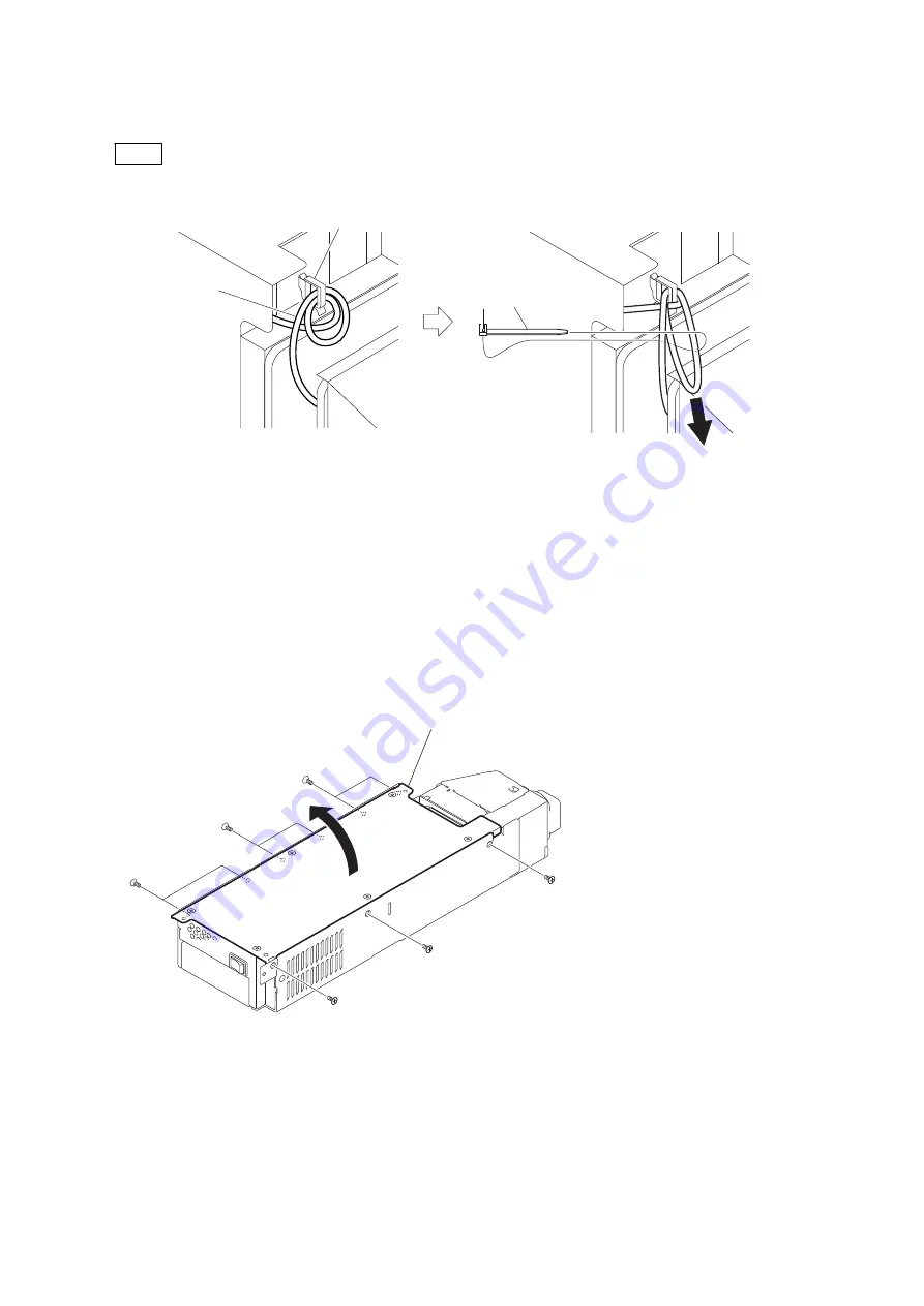
Draw the slack of the harness in the arrow direction and clamp it with a tie band as shown in the figure below.
Note
After the harness has been clamped, cut the redundant part of the tie band.
Harness
Harness clamp
Tie band
10. Install the power block assembly (D00) by reversing steps 1 to 2.
4-2-3.
RE-274 Board
Preparation
1.
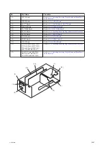
Remove the power block assembly (D00). (Refer to
“4-2-1. Power Block Assembly (D00)”
2.
Disconnect the harness from the connector CN8003 on the RE-274 board. (Refer to
)
Procedure
1.
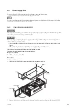
Remove the nine screws, and remove the cover (EK) in the arrow direction.
K3 x 6
K3 x 6
K3 x 6
K3 x 6
K3 x 6
K3 x 6
Cover (EK)
2.
Disconnect the harnesses from the connectors CN601, CN6001 and CN6002 on the RE-274 board.
HDCU2500
4-7
Содержание 10001
Страница 6: ......
Страница 12: ......
Страница 14: ......
Страница 25: ...1 5 Outside Dimensions HD CAMERA CONTROL UNIT 1 5 200 1 3 7 1 4 7 2 1 9 Unit mm HDCU2500 1 11 ...
Страница 118: ......
Страница 130: ...Harness BOARD1 and Harness BOARD2 Upper Side Harness BOARD1 Harness BOARD2 Lead pin RE 274 board HDCU2500 4 12 ...
Страница 148: ......
Страница 161: ...B 1000 7 mVp p 75 Ω termination EN 159A 159B board Side A A B C D E F G H J 1 2 3 4 5 RV305 B A NTSC PAL HDCU2500 5 13 ...
Страница 162: ......
Страница 264: ......
Страница 357: ...Section 9 Board Layouts ADO 12 CN1 CN2 CN5 A SIDE SUFFIX 11 ADO 12 B SIDE SUFFIX 11 ADO 12 HDCU2500 9 1 ...
Страница 368: ...EN 159A EN 159B The location is described at the end in this section A SIDE SUFFIX 11 EN 159B EN 159A HDCU2500 9 12 ...
Страница 369: ... B SIDE SUFFIX 11 EN 159B EN 159A HDCU2500 9 13 ...
Страница 374: ...PS 778D00 B SIDE SUFFIX 11 HDCU2500 9 18 ...
Страница 392: ...HDCU2500 SY HDCU2500 CE J E 9 968 889 01 Sony Corporation Printed in Japan 2012 1 08 2012 ...


