SONOPLOT MICROPLOTTER II Скачать руководство пользователя страница 1

M

ICROPLOTTER

™ II

M

ANUAL


R

EVISION

 2.2 

Содержание MICROPLOTTER II

Страница 1: ...MICROPLOTTER II MANUAL REVISION 2 2 ...

Страница 2: ...SONOPLOT INC 3030 LAURA LANE SUITE 120 MIDDLETON WI 53562 608 824 9311 CONTACT SONOPLOT COM 2 ...

Страница 3: ...ple Application 20 One component oligonucleotide microarray 20 Wires from nanometallic inks 28 SonoGuide 30 Overview 30 Main interface 30 Directional controls 32 Toolbar items 33 Saving positions 34 Robotic positioner settings 35 Printing patterns 37 Camera display 40 Camera settings 41 Dispenser control 43 Dispenser calibration 45 Solution well locations 46 Surface cant calibration 49 Rotational ...

Страница 4: ...Dispenser refurbishing 59 Revision History 61 4 ...

Страница 5: ... Microplotter among others are trademarks of SonoPlot Inc in the United States and other countries Other parties trademarks or service marks are the property of their respective owners and should be treated as such The Microplotter products and accessories are protected by one or more of the following U S Patents 6874699 7467751 5 ...

Страница 6: ......

Страница 7: ...oliters of fl uid to a surface in order to create features as small as 20 micrometers microns wide due to its use of a novel form of fl uid ejection based on ultrasonic pumping The dispenser at the core of a Microplotter system is composed of a hollow tapered glass needle attached to a piezoelectric element When an alternating current is supplied to the piezoelectric it vibrates At certain frequen...

Страница 8: ...spot on a surface but not deactivating the dispenser after fl uid contact has been made with the surface Instead the dispenser is moved along the surface in a straight line leaving behind a smooth line wherever it passes Only when the line is fi nished is the dispenser deactivated and retracted from the surface Aqueous solution being deposited in a 50 micron diameter spot 7 ...

Страница 9: ...ot be of much use without a precision positioning system to place that dispenser at select locations and do so in an automated fashion The robotic positioner of the Microplotter system occupies most of its physical volume and can move the dispenser over a 31 x 31 x 7 cm volume with a 10 micron resolution in the X Y and Z axes All of this movement is controlled through the SonoGuide software packag...

Страница 10: ......

Страница 11: ... and optics system already mounted iMac control computer with keyboard and mouse Control electronics A box containing cables for attachment of the various components Additionally SonoGuide the primary interface for your Microplotter system will need to be installed to a controlling computer Positioning system After unpacking the fi rst step in the setup process is to move the positioning system in...

Страница 12: ...Power cable Positioning stage X axis cable Positioning stage Y axis cable Positioning stage Z axis cable 10 ...

Страница 13: ... USB cable from the electronics box into a USB port on your computer and also insert the USB cable from the CCD camera to a different USB port on your computer This step is shown below on a Mac computer The process is the same for a Windows computer USB cable to control computer RJ11 cable to dispenser 11 ...

Страница 14: ...ternal devices connect the USB cable for that to the computer and connect the power leads to the appropriate terminals on the device to be controlled Finally plug in the power connectors to the control electronics Insert the USB cable for connecting to the control electronics Insert the USB cable from the CCD camera 12 ...

Страница 15: ...Guide software on your computer MacOS Go to www sonoplot com downloads and click on the SonoGuide for Mac link Download the SonoGuide DMG fi le Once downloaded double click on the DMG fi le The SonoGuide Installer window will appear on the screen Drag the SonoGuide icon over to the Applications folder SonoGuide has now been installed to your MacOS computer 13 ...

Страница 16: ...Windows Go to www sonoplot com downloads and click on the SonoGuide for Windows link Download the SonoGuideInstaller exe Once downloaded run the installer Select the Installation Folder 14 ...

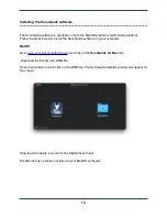
Страница 17: ...Select the components to install Select where you would like to create SonoGuide s shortcut 15 ...

Страница 18: ...SonoGuide is ready to be installed Click Install to start installing SonoGuide Once the installer has fi nished installing SonoGuide click on Finish SonoGuide has been installed and is ready to use 16 ...

Страница 19: ...cting the exposed glass needle to any surface as even a slight touch can shatter the fragile tip To load a dispenser cartridge carefully place the notched side of the dispenser onto the printhead as shown Plug the RJ 11 cable into the RJ11 adapter 17 ...

Страница 20: ...front of the control box When the system is powered on the green power light and orange COMM light will be illuminated on the front of the box Double click on the SonoGuide icon to open the controlling software SonoGuide described in detail in Chapter 4 is your primary interface with a Microplotter system allowing you to manually move the positioner automatically dispense complex patterns control ...

Страница 21: ...Fully installed Microplotter II system 19 ...

Страница 22: ......

Страница 23: ...a Microplotter instrument to lay down continuous lines These examples assume that the system has been properly installed as described in Chapter 2 One component oligonucleotide microarray To begin turn on the control computer the positioning system and the controlling electronics Once the computer has booted itself to the desktop click once on the SonoGuide This will start up the SonoGuide control...

Страница 24: ...pport microscope slides either replace the deck with one that does or use a different substrate material After loading the slide clip into place a new dispenser if one is not already in the system Connect its telephone wiring to the jack on the Z axis As soon as the new dispenser s wiring is connected select Calibrate Dispenser from SonoGuide s main control interface The software will then calibra...

Страница 25: ...y opening the Camera Controls from the windows options and adjusting the sliders in the dialog that will appear Close this window when fi nished Now that the dispenser and camera are set up properly it is time to measure the topography of the microscope slide To do this the dispenser will need to be moved close to the surface Use the directional buttons on the upper left portion of the main SonoGu...

Страница 26: ...over shooting the surface too far will damage the glass needle Change the large step size to 1000 microns one millimeter and more fi nely position the dispenser relative to the surface of the microscope slide Click on the Find surface button above the manual controls to have the dispenser move down slowly and detect the height of the surface If this stops before the dispenser is visibly contacting...

Страница 27: ...ave been entered press the Calibrate surface cant button to begin the surface topography measurement The dispenser will move down until it contacts the surface the position will be measured and then the dispenser will pick up and move to a new location The software measures 5 points in a line along both the X and Y axes to determine the cant of the surface This process should take a few minutes to...

Страница 28: ...l be easy to return to later To do this click on the button in the Positions window This will create a new position and leave you able to edit its name Type in Above slide and hit Return when you are done The new position is added to the list of saved positions meaning that it will be easy to return here in the future It is now time to load solution into the dispenser Place approximately 50 microl...

Страница 29: ...n to add a new solution to the list Enter in a name of Solution 1 and hit Return when you are done Click Set Custom Position to set this up as a custom position using the current coordinates When the glass tip of the dispenser dips into solution that solution should start rising up the inside of the dispenser through capillary action as shown in the following illustration 26 ...

Страница 30: ...ove the dispenser 2 4 millimeters to your right and towards you to better center the pattern on the slide With the addition of fl uid to the dispenser there is the possibility that its vibrational properties have changed so it s recommended that you recalibrate it before dispensing To do this click on the Calibrate dispenser toolbar item followed by clicking on the Scan button in the calibration w...

Страница 31: ...positioner to its safe resting location and remove the fi nished microarray from the deck of the Microplotter system Wires from nanometallic inks A typical microelectronic application of a Microplotter instrument is in the dispensing of nanometallic inks to form conductive wires pads and to repair open circuits These nanometallic inks vary in composition but some have many of the same properties o...

Страница 32: ...e SonoGuide window to switch back to that application Manually move the dispenser over to the well containing the ink to be deposited and down into the ink until the tip is below the fi ll level of the well The ink should start fi lling the dispenser through capillary action If not please refer to the previous section or Chapter 6 You may also set the position of this well as described above Move ...

Страница 33: ... windows and arrange these windows in any fashion the user fi nds useful Main interface Upon starting SonoGuide it will check with the robotic positioner of the Microplotter system to determine its status If either the positioner or the controlling electronics are not turned on or the cables between the computer the electronics and the positioner are disconnected SonoGuide will warn that it is una...

Страница 34: ... been homed it will prompt you that it is about to do so Warning Clear the working area of the Microplotter system and make sure that no one is near the volume covered by the robotic arm as the positioner will move quickly to home itself Physical injury may result if a person is near the arm while it is moving and any obstructions to the path of the robotic arm may damage the robotics the dispense...

Страница 35: ... starting with the directional controls Directional controls The window for the directional controls appears as follows These controls allow you to move the positioner manually in a stepwise fashion or a continuous fashion There are two sets of buttons those with a single arrow and those with two arrows These allow the you to move the positioner in a stepwise fashion The single arrow buttons 32 ...

Страница 36: ...heir home points Warning The home move travels over a large distance and can be very fast so make sure that all objects and personnel are clear of the positioner s working range before clicking on this button The next item is a Find surface item The electronic surface sensing technology within the Microplotter dispense head can be used to detect the exact surface height a very useful function for ...

Страница 37: ...ion highlight a position by clicking on it and press Crosshairs This will cause the dispenser to pick up to a set height the setting of which will be explained in the next section move over to the correct X Y coordinate and move the print head back down to the necessary height To save the current position in order to return to it quickly at a later time click on This will insert a new position int...

Страница 38: ...r is being moved manually and when the movement is controlled by the computer during the automatic deposition of a pattern For example it might be desirable to have faster speeds and accelerations set for manual positioning than for automatic positioning so that you can quickly move the dispenser over a large area in order to align it above a speci fi c position and then have it move much more slo...

Страница 39: ...s By enabling this option the system will cause the dispenser to approach the surface in smaller steps and use a more sensitive detection routine The downside to this is that the approach to the surface will be much slower than the standard technique This window also contains settings for the proportional integral derivative PID control loop of the system motors Unless instructed to do so these va...

Страница 40: ... loaded in this manner Once a pattern has been loaded it will be previewed in the middle of the main interface A crosshair indicates the current position of the dispenser relative to the rest of the pattern and its location will always be in the middle of the pattern or DXF fi le If a portion of the pattern cannot be printed because it extends outside of the working area of the system that part of...

Страница 41: ...heir name Only the enabled and visible layers will be printed These layers can be associated with solution wells that have been laid out in SonoGuide by clicking next to them in the Solution Well column and choosing one of the solution wells This will associate that layer with that solution and will cause the dispenser to be loaded with that solution as needed before the layer is printed See the S...

Страница 42: ... stay at the last location in a pattern when done as opposed to the normal process of returning to the start on print completion with the second option The third option lets the system optimize the pattern printing Usually in a right to left top to bottom motion This window also allows you to override the dwell time when printing droplets The units are in milliseconds When dispensing a pattern the...

Страница 43: ...ime display from the CCD camera pointed at the tip of the fl uid dispenser The high magni fi cation optics surrounding the CCD have a fi eld of view that is approximately 1200 microns 1 2 mm across and can resolve features as small as 5 microns wide LED illumination is provided to enhance viewing in low light conditions Aside from providing feedback for the dispense process and enabling entirely m...

Страница 44: ... save the snapshot to Additionally you can select the image format of the snapshot from a range of different types with many quality options to choose from At the top of the main user interface there are a series of other helpful toolbar items In addition to the already described camera controls there are options to bring up other windows for controlling various aspects of the Microplotter system ...

Страница 45: ...d be used with Exposure to tune the camera input for different lighting conditions Brightness The overall brightness of the camera image too high and it can reduce the contrast of the image too low and the image may be too dark to see Exposure A value representing the exposure time of the camera CCD with higher values allowing for the imaging of even dark scenes This is the primary setting along w...

Страница 46: ...spraying action within a hollow cavity Settings for controlling the behavior of the dispenser can be found under Dispenser Show dispenser controls or the Control dispenser toolbar item In the default view the strength of applied ultrasonics when dispensing and when spraying can be modi fi ed These strengths are in terms of the voltage applied to the piezoelectric element within the dispenser Lower...

Страница 47: ...From this view you can manually activate the dispensing or spraying process by clicking on the Dispense or Spray buttons respectively The dispensing or spraying action will take place for the duration speci fi ed in the text fi eld underneath the appropriate voltage setting If you wish to have even fi ner control over the dispenser settings you can click on the disclosure arrow to the left of the ...

Страница 48: ...ed to be recalibrated due to changes in its contents or drift in the system The connection of a dispenser to the system is not automatically detected Open the Calibrate Dispenser toolbar item to begin the calibration process A calibration can be triggered by clicking on the Calibrate button A trace will be displayed as the dispenser is scanned followed by a brief progress indicator during the fi n...

Страница 49: ...ion dialog either choose the menu item Dispenser Perform Dispenser Calibration or the Calibrate dispenser toolbar item Solution well locations The Microplotter has the ability to dispense multiple solutions when printing patterns To do this the dispenser will use higher intensity ultrasonics the Spray settings seen earlier to forcibly eject fl uid from the dispenser The procedure for switching sol...

Страница 50: ...ution has been selected its properties will appear on the Solution Settings window In addition to solution wells locations for rinse solvents and waste wells can be set These can be shared between solutions or they can be different for each solution The easiest way to set up many solutions is to place those solutions within a 96 or 384 well micro titer plate If you have done this then all you need...

Страница 51: ...e it takes to spray all of that solution out of the dispenser and the number of rinse cycles required to fully clean out that solution from the dispenser Each solution can be set to either return solution back to its original solution well when done or to eject it into a designated waste well The waste well can be chosen from any of the solution wells you have added The same goes for the well to u...

Страница 52: ...time of a dispenser can be prolonged by preventing positioning overshoot that might damage a dispenser s fragile tip The application of this surface sensing has been described in the Main interface and Robotic positioner settings sections The ability of a Microplotter dispense head to electronically sense contact with the surface allows the system to calibrate the cant of a fl at surface Every fl ...

Страница 53: ...rtical directions After the sensing run has completed the cant of the surface in X and Y will be calculated stored and reported in this window This is expressed as a slope the number of microns to rise for every micron out in that direction Values of 0 0001 to 0 005 are typical for apparently level surfaces The calculated cant will be used with automatically dispensed patterns to calculate the cor...

Страница 54: ...bration will be used for every pattern printed after this point until you clear the calibration To clear the calibration click on the Clear rotational calibration button at the bottom of the dialog box Diagnostics For troubleshooting purposes the response of the surface sensor can monitored in realtime To display the feedback from the sensor choose the Window Diagnostics menu item At regular inter...

Страница 55: ...rface sensor as described in the previous section When retracted from the surface the signal should sharply drop off once again If this behavior is not observed repeat the calibration and try again This sensor feedback can be monitored at any time while working with the dispenser and can be useful when moving the dispenser around manually in order to verify that contact has been made with a surfac...

Страница 56: ...angle next to the Advanced label This will expose a series of realtime readouts from the ultrasonic frequencies used to determine when contact has been made with a surface This can be used by SonoPlot personnel to help fi gure out why a given dispenser may not be behaving properly 53 ...

Страница 57: ...cuts Find Surface Ctrl Cmd F Set A1 position Ctrl Cmd 1 Move to desired position Ctrl Option click Go Home Fn Left arrow MacOS Go Home Home key Windows When using Trackball Hold SHIFT to move 10X When using Manual buttons Hold SHIFT to move 10X Hold Ctrl Cmd to move 1 10X Print Ctrl Cmd P 54 ...

Страница 58: ......

Страница 59: ...ide of the dispenser s tip Other polymers may harden to the point where solvent is unable to dissolve the polymer permanently sealing it shut SonoGuide gives the error message Positioner is not connected The control electronics and positioner must be turned on to allow the computer to communicate with the positioner Turn on the electronics box and positioner then click OK in the warning dialog box...

Страница 60: ...re on the dispensing tip Sonoplot suggests moving the tip down to a short distance above the surface then stepping down in 10 micron steps until a fl uid bridge is made between the tip and the surface It will require some experimentation to determine the voltage required to dispense the fl uid without spraying Also be sure that you have calibrated for the cant of the surface to ensure that the tip...

Страница 61: ...p the sensor diagnostics dialog by choosing the Dispenser Show Diagnostics menu item as described in Chapter4 This window displays the realtime readout from the surface sensor A red line indicates the sensor threshold for when the software will register contact with the surface When the dispenser is above the surface the signal should be below this line Upon contact with the surface the signal sho...

Страница 62: ......

Страница 63: ...sition variability As low as 10 Viscosity 450 cP Positioning 35 x 30 x 7 cm X Y Z axes 5 µm resolution Calibration Automatic surface height calibration Camera USB 3 0 with digital video capture Software SonoGuide Dimensions 86 4 x 71 1 x 48 3 cm 34 x 28 x 19 in Weight 91 kg 200 lbs Power 3 0 A for 100 200 V or 1 5 A for 220 240 V 58 6 ...

Страница 64: ......

Страница 65: ...opipette from the wide end by scribing the glass and breaking it Use a scoring wafer such as the Sutter ceramic scoring wafer www sutter com part number CTS Reassemble the dispenser by replacing the RJ11 cable into the cartridge body Using alligator clips or helping hands orient the dispenser so that the piezoelectric element is facing up Apply a very thin bead of glue to the edge of the piezoelec...

Страница 66: ...60 ...

Страница 67: ... chapter to include new version UI features Version 2 1 Added the polygon pattern element to Chapter 9 Version 2 1 Revised the SonoGuide chapter to include the new pattern preview window and DXF import capabilities Version 1 0 Initial revision 61 8 ...

Отзывы: