background image

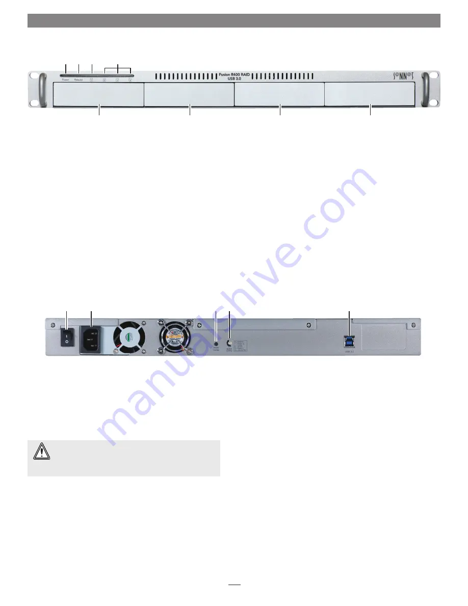
1 – Fusion R400 RAID USB 3.0 Features

1

➊ ➋

➑ ➒

  1 –  Power Indicator LED 

This blue LED lights when the Fusion R400 RAID USB 3.0 is 
powered.

  2 –  Rebuild Indicator LED 

This orange LED lights when the Fusion R400 RAID USB 3.0 
is rebuilding the data on a RAID 5 or 10 RAID set.

  3 –  Mode Change Confirmation; Drive 1 Presence, Activity, 

and Fault Indicator LED 

This LED lights red when the Drive Mode Change Switch 
is pressed. It also indicates Drive 1’s ready state (solid green), 
read and write activity (flashes green), and fault status (OFF). 
Note that the LED will remain off if the drive in drive bay 1 
is not recognized.

  6 –  Power Switch

  7 – Power Cord Socket

  8 –  Drive Mode Change Switch 

Press and hold this switch for three or more seconds to 
activate the selected drive mode.

  4 –  Presence, Activity, and Fault Indicator LEDs for  

Drives 2 – 4 

These LEDs indicate the ready state (solid green), read and 
write activity (flashes green), and fault status (OFF) for drives 
2 – 4. Note that an LED will remain off if the corresponding 
drive is not recognized (or if no drive is installed).

  5 –  Drive Tray


To remove a drive tray, press its handle in until it pops out, 
then pull out the entire tray. To insert a drive tray, insert it 
into the drive bay until it stops, and then push its handle in 
until it latches closed.

  9 –  Drive Mode Setting Switch 

Select the drive mode setting using this switch.

10 –  USB 3.0 Interface Port 

This port is compatible with the included Sonnet USB 3.0 
cable and other USB 3.0 cables. It is also compatible with 
USB 2.0 cables. However; when a USB 2.0 cable is used, the 
R400 RAID USB 3.0’s performance will be reduced by as much as 
85 percent
.


 WARNING:

 Once you press and hold the Mode Change 

Switch for more than three seconds while the R400 RAID 

USB 3.0 is powered, any files stored on the system are lost and 
cannot be recovered! 

Содержание Fusion R400

Страница 1: ...1U Rackmount 4 Drive Hardware RAID 5 SATA Storage System with USB 3 0 Interface FUSION R400 RAID USB 3 0 User s Guide For Windows ...

Страница 2: ......

Страница 3: ... Just a Bunch of Disks 4 Drive Mode Configuration Instructions 5 General Information Select Drive Mode 5 Drive Formatting Instructions 6 OS X Users Instructions Windows 8 7 Vista and Server 2012 2008 Users Instructions Linux Users Information 6 Status LED Indications 7 System Powered No Data Reads or Writes Drive Activity Drive Not Recognized RAID 5 or RAID 10 Rebuild Bad Drive Detected 7 Specific...

Страница 4: ...This page left intentionally blank ...

Страница 5: ...rives 2 4 These LEDs indicate the ready state solid green read and write activity flashes green and fault status OFF for drives 2 4 Note that an LED will remain off if the corresponding drive is not recognized or if no drive is installed 5 Drive Tray To remove a drive tray press its handle in until it pops out then pull out the entire tray To insert a drive tray insert it into the drive bay until ...

Страница 6: ...he handle in until it clicks to secure the drive module inside the enclosure Figure 4 8 Repeat steps 3 7 for the remaining drives and then install the Fusion R400 RAID USB 3 0 into the rack or set it on the surface which it will reside Connect the Fusion R400 RAID USB 3 0 to Computer and Power Outlet 1 Using the supplied USB 3 0 cable connect the Fusion R400 RAID USB 3 0 to a USB 3 0 port on your ...

Страница 7: ...ripe set is lost See Figure 5 When configured as a RAID 0 volume the volume size is equal to the full capacity of the drives RAID 10 Striping Mirror Spans Two Drives RAID 10 increases data transfer rates while ensuring security by writing the exact same data simultaneously to two or more different drives Any one of the four drives can fail and the volume will continue to function RAID 10 is used i...

Страница 8: ...l unformatted capacity is 16TB After configuring the drives in RAID 5 mode approximately 12TB is available for storage with the other 4TB set aside for parity JBOD Just a Bunch of Disks JBOD mode enables all four drives to be available individually at the same time for normal storage operations See Figure 9 JBOD provides no data protection JBOD offers the full capacity of each of the drives Disk 1...

Страница 9: ...ess and hold the MODE Change switch for more than three seconds Figure 11 the Drive 1 LED will light red while the LEDs for Drives 2 4 will light green until you release the button Figure 11 Once you release the button all four drive LEDs will flash green as the mode change takes place 4 Turn on your computer you may now format the drives using your computer s operating system drive formatting app...

Страница 10: ...k Disk Management 3 When the Initialize Disk window appears select the RAID volume you created Select the MBR partition style if you need to access your RAID storage from a computer running Windows XP Professional or 32 bit Windows Server 2003 otherwise select GPT Click OK 4 In the Disk Management window the Fusion R400 RAID USB 3 0 s drives will appear listed as unallocated as a single volume unl...

Страница 11: ... is a small chance that the enclosure is defective RAID 5 or RAID 10 Rebuild After inserting a drive into the R400 RAID USB 3 0 enclosure to replace a failed drive from a RAID 5 or RAID 10 group or putting in a new drive to be cloned to the Rebuild LED lights up orange and the Drive LEDs flash with activity until the RAID has been rebuilt or the clone copy completed Figure 15 Once the rebuild is c...

Страница 12: ... computers with an eSATA interface External Connector One USB 3 0 Data Transfer Speed Up to 250 MB s depending on interface used and drive configuration OS Support Platform independent Supported Drive Configurations Hardware based RAID 0 5 and 10 span and JBOD Power Supply Universal 220W 100 240V AC 50 60Hz Operating Temperature 32 to 104 F 0 C to 40 C Dimensions WxDxH 17 0 x 16 25 x 1 75 in 43 2 ...

Отзывы: