background image


HY02 

DIGITAL

 AUTOMATIC 

TELEPHONE BALANCE UNIT 

USER HANDBOOK  


DHY 02S 

Single automatic TBU, rack mounted with PSU. 

DHY 02T 

Twin automatic TBU, rack mounted with PSU. 

DHY 02SR  Single automatic TBU, with ringing detector. 
DHY 02TR  Twin automatic TBU, with ringing detector. 


SONIFEX LTD, 1995.  

All Rights Reserved  

Revision V1.00c, June 1995 


61, Station Road, Irthlingborough, 

Northants., NN9 5QE, England. 

Tel : +44 (0)1933 650 700  

Fax : +44 (0)1933 650 726 


Information in this document is subject to change without notice and does not represent a commitment on the part of Sonifex Ltd.  No 
part of this manual and/or databases may be reproduced or transmitted in any form or by any means, electronic or mechanical, 
including photocopying, recording, or information storage and retrieval systems, for any purpose other than the purchaser’s personal 
use, without the express written permission of Sonifex Ltd. 


Unless otherwise noted, all names of companies, products and persons contained herein are part of a completely fictitious adaptation 
and are designed solely to document the use of Sonifex products. 


Содержание HY02 DIGITAL

Страница 1: ...rmation in this document is subject to change without notice and does not represent a commitment on the part of Sonifex Ltd No part of this manual and or databases may be reproduced or transmitted in any form or by any means electronic or mechanical including photocopying recording or information storage and retrieval systems for any purpose other than the purchaser s personal use without the expr...

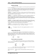
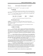
Страница 2: ...t to complete the WARRANTY REGISTRATION DOCUMENT and return it to Sonifex Ltd 61 Station Road Irthlingborough Northants NN9 5QE ENGLAND The registration document carries the following information for servicing SERIAL NUMBER DHY______ COUNTRY CODE E A U O Safety Of Mains Operated Equipment HY02 Digital TBU Preparing the Machine for Use Each HY02 Digital TBU is shipped in protective packaging and sh...

Страница 3: ...he B T plug should be disconnected from the telecommunications network before disconnecting the earth Disconnection of this earth connection may render the equipment unsafe with a consequential possible electrical shock hazard from exposed metallic parts WARNING The barriered ports NTTP and Handset must not be connected directly or indirectly to the unbarriered ports Line Input Line Output or Remo...

Страница 4: ...re limited to 90 days and one 1 year respectively or the shortest period permitted by applicable law whichever is greater Customer Remedies Sonifex s entire liability and your exclusive remedy shall be at Sonifex s option either a return of the price paid or b repair or replacement of the SOFTWARE or hardware that does not meet Sonifex s Limited Warranty and which is returned to Sonifex with a cop...

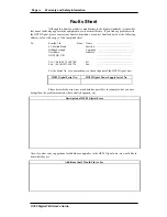
Страница 5: ... To Sonifex Ltd From Name 61 Station Road Position Irthlingborough Company Northants Address NN9 5QE UK Tel 44 0 1933 650 700 Tel Fax 44 0 1933 650 726 Fax For the Serial No of your machine see the back panel of the HY02 Digital unit HY02 Digital Serial No HY02 Digital Power Supply Serial No Please describe the error in as much detail as possible for example what you were doing when the problem oc...

Страница 6: ...ropriate BT socket or sockets installed in order to use this equipment then this form should be sent to your local telephone area office Name Company Address Equipment Type Sonifex HY02 Digital Telephone Balance Unit BABT Approval Number NS 3619 123 L 601748 To British Telecom Area Office Please supply a BT line socket for connection of the above apparatus to A new line An existing line at the abo...

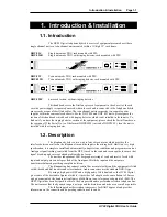
Страница 7: ...n The telephone hybrid is a two wire to four wire converter which provides the interface between a caller on the telephone line and the input to the mixing desk Built to a very high specification it is simple to install and automatically adapts to line conditions and programme content Analogue signal limiting controlled from the DSP is used in the send and receive paths to ensure that signal break...

Страница 8: ...ine 1 2 5 Specified Systems The HY02 Digital is suitable for connection to any exchange line forming part of a Public Switched Telephone Network PSTN or a Relevant Branch system for PSTN lines or any extension This equipment is not suitable as an extension to a payphone A definition of a Relevant Branch System for PSTN is given in BS6789 Section 6 1 1986 clause 2 4 including the NOTE to that claus...

Страница 9: ...hen ceases to comply with the standards against which approval was gained 1 2 11 Statutory Mark Approved for connection to telecommunications systems specified in the instructions for use subject to the conditions set out in them 1 3 Specification Feature Value Clean feed input line 10kΩ balanced 0dB Clean feed limiting input 6dBu Bandwidth to Telephone line 250Hz 3500Hz 3dB ref 1kHz Telephone lin...

Страница 10: ... telephone line The output of the digital hybrid unit is normally 0dBu from a balanced source of 50 ohms or less across the useful bandwidth of the equipment The bandwidth is restricted by the line conditions between 250 Hz and 3 5 kHz The output stage is capable of driving into 600 ohm loads at up to 8dBu It is not necessary to terminate this output Isolation of better than 69dB is created betwee...

Страница 11: ...te a call lift the Handset and dial the required telephone number When the call has been established press the Line Connect switch and the call will be handed over to the telephone hybrid unit To clear the line at the end of the call press the Line Connect switch The Line Connect switch lamp is off in the non connected mode and on in the connected mode Please note that any adjustments and settings...

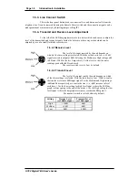
Страница 12: ...ed With the switch set to low a 12dB signal received is output at 0dB Selecting the Medium or High settings add 6dB and 12dB to the level respectively Set the level so that the meter readings peak at the 0dB scale mark The receive switch is set to Low by default 1 6 4 2 Transmit Level The level of the output sent by the unit depends on which of the three settings is selected With the switch set to...

Страница 13: ...o reasons why the clean feed signal is needed Firstly the TBU is designed to separate the caller audio from the desk output audio with an output consisting mostly of the caller audio If the caller audio is sent to the TBU send input a feedback loop is created causing howling on the line and the hybrid can not separate the two signals Secondly the caller should hear what the other listeners are hea...

Страница 14: ...Page 1 8 Introduction Installation HY02 Digital TBU User s Guide This page deliberately blank ...

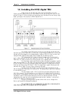
Страница 15: ...low in D1 and D2 D7 D8 rupturing fuses F1 F2 F3 F4 removing the overvoltage condition 2 2 Electronic Digital Hybrid Unit Circuit Description The electronic digital hybrid unit comprises the following sections see block diagram Figure 2 1 2 2 1 Input circuits and limiter 2 2 2 Telephone line barrier and transformer 2 2 3 Output circuits 2 2 4 Divert switch logic 2 2 5 Line balancing electronics 2 2...

Страница 16: ...Page 2 2 Circuit Description Controls HY02 Digital TBU User s Guide ...

Страница 17: ...dance push pull amplifier driving the output balancing transformer TR3 The diodes D21 and D22 R72 and R71 form a bias chain for the drive transistors The input at Q2d is filtered by R79 and C43 a simple low pass filter The balanced output at TR3 is less than 50 ohms at the frequencies used and has a high common mode rejection The output signal at TR1 consists of the telephone line signal only with...

Страница 18: ...ented 2 2 5 1 Duplex Control Transmit receive path level locking Off position No processing Low position 12dB dynamic levelling High position 24dB dynamic levelling Attack and release time 1dB per 5msec Hysteresis 8dB for no processing 2 2 5 2 Adaption System Network cancellation of 28ms Double talk detection and normalised adaptive FIR system used with pink noise cancellation 2 2 5 3 Send Circuit...

Страница 19: ... are processed via the DSP These have hysterisis built in to minimise chattering The divert relay and two four wire mode control is driven via the DSP The signal is checked for overload and digitally limited if needed The Tx LED is turned on if the outgoing signal is above 14dB and the Tx signal is gain reduced if found to be below 24dB The Tx level is adjusted before being sent to the codec send ...

Страница 20: ...nt panel which provide general information about the equipment A status LED shows that the equipment is on A line hold LED indicates that a telephone line is seized and connected Additionally there are independent LED bar graph displays of 10 elements each showing the relative levels of both the received and transmitted signals The presence of signals within the normal zone up to the maximum level...

Страница 21: ...set on pins 1 2 do not adjust JP7 Link for instant reset JP8 Controls disconnect tones Set for single tone unset for dual tone UK JP9 Controls disconnect tones Set for pulse tone Belgium France unset for continuous disconnect UK JP10 Controls disconnect tone burst Set for long burst 4 secs unset for short 2 secs disconnect tone burst UK It is the length of time that the line tone has to be present...

Страница 22: ...Page 2 8 Circuit Description Controls HY02 Digital TBU User s Guide ...

Страница 23: ...nector XLR 3 31 10k ohm balanced floating Pin 1 Screen Pin 2 Phase Pin 3 Non phase 3 1 3 Line Output The line output is an XLR 3 pin male connector XLR 3 32 10k ohm balanced floating Pin 1 Screen Pin 2 Phase Pin 3 Non phase 3 1 4 Remotes The HY02 Digital is equipped with a 5 way IP40 connector which is assigned as follows Pin 1 Lamp Hybrid Unit 1 Pin 2 Divert Switch Line Connect Hybrid Unit 1 Pin ...

Страница 24: ...are connected to the central power supply by a 7 way IP 40 connector with the following assignments Pin 1 15V Pin 2 15V Pin 3 Common Pin 4 Earth Pin 5 Earth Pin 6 Remote line connect switch Pin 7 Remote line connect lamp 3 1 6 Protective Earth Terminal This terminal must be connected ...

Страница 25: ...Page 0 Index HY02 Digital TBU User s Guide ...

Страница 26: ...5 1 5 2 Making a Call 1 5 1 6 Front Panel Controls and Displays 1 5 1 6 1 LED Indicators 1 5 1 6 2 Bar Graph LED s 1 5 1 6 3 Line Connect Switch 1 6 1 6 4 Transmit and Receive Level Adjustment 1 6 1 6 4 1 Receive Level 1 6 1 6 4 2 Transmit Level 1 6 1 7 Questions and Answers 1 7 2 Circuit Description Controls 2 1 2 1 Mains Power Unit Circuit Description 2 1 2 2 Electronic Digital Hybrid Unit Circu...

Страница 27: ...HY02 Digital TBU User s Guide ...

Страница 28: ...n of Liability iii Limiter 2 1 Line Balancing Circuitry 2 4 Line Connect Switch 1 5 Line Input Connections 1 4 3 1 Line Output Connections 1 4 3 1 M Mains Lead Connection ii Model Types 1 1 N NTTP Port connection 1 4 O Options 2 7 Output Circuitry 2 3 P Potentiometer Settings 2 7 Power Connections Between Power Supply TBU 3 2 Power Connector 3 1 Power Supply Circuit Description 2 1 Connections 1 1...

Отзывы: