background image

1

EN

 - GDK 700 installation and operating guide - SOMFY

EN

Contents

Product description 

2


Kit contents 

2


Space requirements 

3


General view of the installation 

3

Field of application 

4


Types of doors which can be motorised 

4


Maximum dimension of doors 

4

Prerequisites for installation 

5


 Tools and screws necessary for installation  
(not supplied) 

5


 Recommendations for fastening  
(screws not included in the kit) 

5

Installation 

6

1.1  Implementation of fastenings 

6


Fastening the lintel and door brackets 

7


Assembling the rail in 3 sections 

9

1.2  Assembly 

9


Assembling the bulb 

10


Assembling the rail to the motor head 

10


Fastening the unit to the ceiling 

11

1.3  Mounting 

11


Fastening the unit to the lintel bracket 

11


 Fastening the link arm to the door  
and the carriage 

        12

1.4  Settings 

13


Adjusting and fastening the opening stop 

13


Checking the tension of the belt 

13

1.5  Electrical connection to the power supply 

14

1.6  Assembling/disassembling the cover 

14

Programming 

15

2.1  Parameter setting 

15


Description of the programming buttons 

15


Performing auto-programming  

15


Checking the mechanical setting of the door 

17

2.2  Advanced settings  

17

2.3  Locking/unlocking the parameters  

menu 

19

2.4  Memorising the remote controls 

20

2.5  Clearing the remote controls 

21

2.6  Reinitialising the settings 

21

Operation 

22

3.1  User training 

22

3.2  Using the remote controls 

22


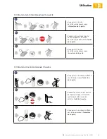
Using the remote control with door closed 

22


Using the remote control with door open 

23


Using a 3-button remote control 

23

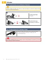
3.3  Obstacle detection mode 

24

3.4  Integrated lighting operation 

24

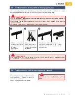
3.5  Manual back release  

mode 

25

3.6  Operation a@er a power outage 

25

Accessories 

26

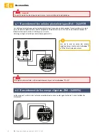
4.1  Connecting the photoelectric cells  

(Ref.: 2400939) 

26

4.2  Connecting the flashing orange light  

(Ref.: 2400596) 

26

4.3  Connecting the remote antenna  

(Ref.: 2400472) 

27

4.4  Connecting the back-up battery  

(Ref.: 2400720) 

27

4.5  Connecting the key contact (Ref.: 2400597) 

28

4.6  Connecting the solar kit (Ref.: 2400961) 

28

4.7  Accessories general wiring diagram 

29

Maintenance and repairs 

30

5.1  Periodic checks 

30

5.2  Diagnostics 

30

5.3  Assistance 

30

5.4  Changing the integrated light bulb 

31

5.5  Changing the remote control battery  

31

Technical data 

32

Translated version of the guide

Содержание GDK 700

Страница 1: ...www somfy com GDK 700 Motorisation pour porte de garage Motorisation for garage door FR Notice d installation et d utilisation 5130194A EN Installation and operating guide ...

Страница 2: ......

Страница 3: ... réglage mécanique de la porte 17 2 2 Paramètres avancés 17 2 3 Verrouillage Déverrouillage du menu des paramètres 19 2 4 Mémorisation des télécommandes 20 2 5 Effacement des télécommandes 21 2 6 Réinitialisation des réglages 21 Utilisation 22 3 1 Formation des utilisateurs 22 3 2 Utilisation des télécommandes 22 Utilisation de la télécommande porte fermée 22 Utilisation de la télécommande porte o...

Страница 4: ...n plafond x 2 F Patte de fixation tête moteur x 2 G Dispositif de débrayage manuel x 1 H Bras de liaison x 1 I Butée fin de course x 1 J Vis auto perceuse TCB H 4 2x13 zn x 2 K Cordon d alimentation x 1 Repère Désignation Qté L Vis rondelle TH10 M8x12 zn x 4 M Vis TH M8x16 zn x2 N Ecrou HU8 x 6 O Axe x 2 P Circlips x 2 Q Vis auto formeuse Ø 4x8 x 4 Ra Rail en 3 parties x 1 Ra1 Manchon x 2 Ra2 Vis au...

Страница 5: ...x 0 5 mm2 C Antenne D Contact à clé 2 x 0 5 mm Longueur hors tout 3154 6 Fixation 2981 7 Rail 2900 Rail 2900 Longueur hors tout 3127 6 Course utile 2555 140 171 mini 63 7 125 65 173 173 113 5 114 269 7 119 6 33 5 152 7 147 1 113 5 269 7 86 5 173 Si la porte de garage est l unique accès au garage prévoir un dispositif de débrayage extérieur réf 2400658 ou réf 9012962 Q Vue générale de l installatio...

Страница 6: ...e pour un usage résidentiel Portes basculante débordante et portes sectionnelles 2 35 H m L m 3 00 2 90 m Surface max 7 m2 Poids max 70 kg Dimension maximale des portes Porte basculante débordante Porte sectionnelle Types de portes motorisables Si le profil supérieur A du panneau est particulier utiliser la chape de fixation B pour porte sectionnelle réf 9009390 A B ...

Страница 7: ...0 Quantité x 2 ou Type M8 x 30 Quantité x 2 Type Vis tôle Ø 6 x 30 Quantité x 4 Type Ø 8 Quantité x 2 Type Ø 8 Quantité x 2 Type Ø 6 Quantité x 4 Type Plastique Ø 10 Quantité x 2 Type Acier Ø 10 Quantité x 2 H Préconisations pour la fixation visserie non incluse dans le kit H Outillage et visserie nécessaires à l installation non fournis Ø 10 mm Béton Acier PZ2 3 5 Ø 3 mm 17 10 13 Béton Acier ...

Страница 8: ...35 D 200 Cas n 2 Motorisation décollée du plafond Si D est supérieure à 200 mm fixer l ensemble de façon à ce que la hauteur H soit comprise entre 10 et 200 mm H distance entre le bas du rail et le point le plus haut de la porte Lorsdel installation centrerl ensemble par rapport à la porte du garage D 200 10 H 200 Pour faciliter la prise de cotes sur le linteau une fois D mesuré déterminer H en ret...

Страница 9: ...linteau soit directement au plafond Centrer la chape porte par rapport à la partie haute de la porte Fixer la chape 1 FR Installation Fixation des chapes linteau et porte Cas n 1 Motorisation collée au plafond Pour une optimisation de la course moteur décaler la chape de 200mm max par rapport au linteau 200 mm max Ø8 x 50 C C Ø8 x 50 Ø6 x 30 Ø6 x 30 D ...

Страница 10: ...OMFY FR 1 Installation C 1 2 Ø8 x 50 Ø6 x 30 Ø6 x 30 Centrer la chape linteau par rapport à la porte du garage Fixer la chape Centrer la chape porte par rapport à la partie haute de la porte Fixer la chape D D C 5 Cas n 2 Motorisation décollée du plafond ...

Страница 11: ...rifier que la courroie présente à l interieur du rail ne soit pas croisée Assemblage du rail en 3 parties 3 Cas n 1 Motorisation collée au plafond Cas n 2 Motorisation décollée du plafond x 16 Dans le cas d une motorisation collée au plafond ne pas utiliser les vis de fixation des manchons Fixer l ensemble à l aide des vis de fixation Les vis de fixation ne doivent pas rentrer dans le rail ne pas ...

Страница 12: ...extrémité du rail Assemblage standard Engager l axe du moteur dans le pignon du rail 3 Assemblage de la tête moteur à 90 pour une optimisation de la course moteur X Serrer l écrou pour tendre la courroie Le caoutchouc s écrase lorsque l on serre Pour une bonne tension le caoutchouc doit mesurer entre 18 et 20 mm distance X Pour fixer l ampoule poser le moteur à plat Appuyer fortement sur l ampoule...

Страница 13: ... le rail au plafond Fixation de l ensemble au plafond 0 Cas n 1 Motorisation collée au plafond 1 2 h 255 mm N L F E Fixer l ensemble au niveau de la tête moteur 0 Cas n 2 Motorisation décollée du plafond 1 2 Positionner l ensemble dans la chape linteau en posant la tête moteur sur le sol ou sur la traverse Fixer l ensemble à la chape linteau N M ...

Страница 14: ...utiliser le kit fixation plafond réf 9014462 3 4 N L Ø8 x 50 1 2 3 G O P H O P Débrayer le chariot à l aide du dispositif de débrayage manuel Amener le chariot au niveau de la porte Fixer le bras à la chape porte et au chariot Dans le cas où la poignée de débrayage est à une hauteur supérieure à 1 80 m il sera nécessaire de rallonger le cordon pour le rendre accessible à tout utilisateur Fixation d...

Страница 15: ... de débrayage manuel et amener la porte en position ouverte Ne pas ouvrir la porte au maximum mais positionner celle ci de façon à ce qu elle n atteigne pas ses butées Positionner la butée contre le chariot et la fixer sur le rail 1 2 1 4 Réglages Réglage et fixation de la butée d ouverture Si nécessaire ajuster la tension de la courroie Le caoutchouc de tension ne doit jamais être totalement compr...

Страница 16: ...ntage Démontage du capot Remonter le capot comme indiqué sur le dessin ci dessus positionner d abord la partie basse du capot dans la fente puis clipser ensuite la partie haute Démonter le capot comme indiqué sur le dessin ci dessus déclipser d abord la partie haute du capot puis ôter la partie basse sans forcer Brancher le câble d alimentation à une prise conforme aux exigences électriques se rep...

Страница 17: ...uyer sur la touche B pour entrer en mode auto apprentissage Le voyant B clignote 2 fois en continu le moteur est en attente d auto apprentissage 2 cas de figure B Cas n 1 Aucun voyant ne clignote Il faut entrer en mode auto apprentissage Fonctions des touches et des voyants Touche A Utilisation du mode marche forcée Sélection d un paramètre Touche B Déclenchement de l auto apprentissage Mémorisati...

Страница 18: ...part en sens inverse par rapport au mouvement précédent Relâcher la touche A avant que le moteur force sur la porte 4 x 2 x 2 Appuyer sur la touche B pour lancer le cycle d auto apprentissage La porte effectue un cycle Ouverture Fermeture complet Si l auto apprentissage est correct le voyant B s éteint Si le cycle d auto apprentissage ne s est pas déroulé correctement le voyant B clignote 2 fois D...

Страница 19: ...e B pour changer la valeur du paramètre Les procédures de programmation ci dessous sont à suivre uniquement si vous souhaitez modifier la valeur des paramètres définie par défaut Voyant A Sensibilité de la détection d obstacle Voyant B Très peu sensible Peu sensible Standard valeur par défaut Très sensible A la fin de l installation vérifier impérativement que la détection d obstacle est conforme à l ...

Страница 20: ...ue la valeur du paramètre voir tableau ci dessous Appuyer sur la touche B pour changer la valeur du paramètre Choix du type d alimentation Voyant A Type d alimentation Voyant B Alimentation secteur type d alimentation par défaut Alimentation solaire 1 2 x 5 N x 5 N Appuyer par impulsions successives sur la touche A jusqu à ce que le voyant A clignote 5 fois Le mode Type d alimentation est activé L...

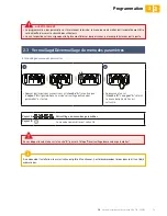
Страница 21: ...a touche A jusqu à ce que le voyant A clignote 4 fois Le mode verrouillage du menu des paramètres est activé Appuyer une fois sur la touche B Le voyant A s éteint Le menu des paramètres est verrouillé A ce niveau de l installation la motorisation est prête à fonctionner Les télécommandes livrées dans le kit sont déjà mémorisées La programmation des paramètres est maintenant terminée le menu des pa...

Страница 22: ...une touche déjà mémorisée provoque l effacement de celle ci 1 2 2 s 5 s Appuyer pendant 2 secondes sur la touche B L éclairage intégré s allume Appuyer sur la touche de la télécommande L éclairage intégré clignote pendant 5 secondes La touche de la télécommande est mémorisée I Mémorisation des télécommandes pour le fonctionnement en Ouverture totale Touche 1 Touche 2 Le clavier de réglage des param...

Страница 23: ...émorisée Mémorisation d une télécommande type Telis ou similaire non fournie dans le kit 7 s 5 s 7 s Appuyer pendant 7 secondes sur la touche B L éclairage intégré s allume puis se met à clignoter 5 secondes Les télécommandes et les réglages sont désormais effacés 2 5 Effacement des télécommandes 2 6 Réinitialisation des réglages Cette procédure provoque l effacement de toutes les télécommandes mémo...

Страница 24: ...réconisations de ce manuel Il est impératif de s assurer qu aucune personne non formée ne puisse mettre la porte en mouvement L utilisateur doit surveiller la porte pendant tout les mouvements et maintenir les personnes éloignées jusqu à ce que la porte soit complètement ouverte ou fermée Ne pas laisser les enfants jouer avec les dispositifs de commande de la porte Mettre les télécommandes hors de...

Страница 25: ...la touche de la télécommande provoque l ouverture de la porte 1 Un appui sur la touche avec la flèche vers le haut provoque l ouverture de la porte 2 Pendant l ouverture ou la fermeture de la porte un appui sur la touche centrale de la télécommande entraîne l arrêt de la porte 3 Un appui sur la touche avec la flèche vers le bas provoque la fermeture de la porte Utilisation de la télécommande porte...

Страница 26: ...tacle fonctionne jusqu à 5 cm du sol Elle est intrinsèque à la motorisation et s opère sans besoin d accessoires cellules photoélectriques L éclairage intégré s allume à chaque mise en route de la motorisation Il s éteint automatiquement au bout de 30 secondes après la fin du mouvement de la porte 3 4 Fonctionnement de l éclairage intégré Une utilisation répétitive donnant lieu à un allumage conti...

Страница 27: ... entraînement vienne se reverrouiller sur le rail de transmission Suite à une coupure de courant la motorisation doit de nouveau reconnaître sa position ouverture totale Lancer une ouverture totale de la porte depuis une télécommande mémorisée La porte s ouvre avec une vitesse dégradée Laisser la porte s ouvrir jusqu à sa position ouverture totale Lors du débrayage de la motorisation un mauvais éq...

Страница 28: ...nique du moteur FR 4 Accessoires Les cellules photoélectriques permettent de détecter la présence d un obstacle pendant l ouverture fermeture de la porte Un obstacle placé entre les cellules empêche la fermeture de la porte Si un obstacle est détecté pendant la fermeture de la porte celle ci s arrête puis se ré ouvre L éclairage intégré est activé par intermittence pendant 30 s Le feu orange est a...

Страница 29: ... fonctionner même en cas de coupure générale de courant Le fonctionnement s effectue alors dans les conditions suivantes Vitesse réduite L éclairage ne fonctionne pas Les périphériques de sécurité sont inactifs Caractéristiques de la batterie Autonomie 24 h 5 à 10 cycles de fonctionnement suivant le poids de la porte Temps de recharge 72 h Durée de vie avant remplacement 3 ans environ Pour une duré...

Страница 30: ...OMFY FR 4 Accessoires 4 5 Raccordement du contact à clé Réf 2400597 4 6 Raccordement du kit solaire Réf 2400961 6 5 7 Le contact à clé permet de commander la manœuvre et l éclairage de la porte de garage motorisée Se référer à la notice du panneau solaire ...

Страница 31: ...essoires Couper l alimentation électrique du moteur avant toute installation d un périphérique C A TX RX B D Repère Désignation Réf A Contact à clé 2400597 B Antenne déportée 2400472 C Batterie de secours 2400720 D Cellules photoélectriques 2400939 E Feu orange clignotant 2400596 F Kit solaire 2400961 E F DANGER ...

Страница 32: ...erie de secours patienter quelques minutes puis re brancher l alimentation Effectuer un cycle d auto apprentissage Si le défaut persiste contacter l assistance technique Somfy 7 Puissance maximum délivrable par le moteur atteinte durant la phase d auto apprentissage Produit en limite de fonctionnement Si la panne persiste ou pour tout autre problème ou demande de renseignement sur votre motorisatio...

Страница 33: ...r l ampoule Manipuler l ampoule avec des gants ou un chiffon Utiliserexclusivementuneampoule24V 20Wmaxi type halogène G4 5 5 Changement de la pile de la télécommande 1 2 3 4 3V CR 2430 3V CR 2430 3V CR 2430 Retirer le clip de la télécommande Soulever le capot Retirer la pile à l aide d un tournevis Remplacer la pile 3 V CR 2430 puis repositionner le capot et le clip de la télécommande ...

Страница 34: ...té Cellules photoélectriques TX RX Entrée de commande filaire Contact sec NO Sortie feu orange Sortie clignotante pour feu orange 24 V 15 W Sortie alimentation accessoires 24 V 500 mA max Entrée antenne déportée Oui compatible antenne RTS Réf 2400472 Entrée batterie de secours Oui compatible pack batterie Réf 2400720 Autonomie 24 heures 5 à 10 cycles suivant porte Temps de charge 72 h Fonctionneme...

Страница 35: ...ption of the programming buttons 15 Performing auto programming 15 Checking the mechanical setting of the door 17 2 2 Advanced settings 17 2 3 Locking unlocking the parameters menu 19 2 4 Memorising the remote controls 20 2 5 Clearing the remote controls 21 2 6 Reinitialising the settings 21 Operation 22 3 1 User training 22 3 2 Using the remote controls 22 Using the remote control with door close...

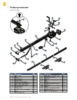
Страница 36: ...ing bracket x 2 F Motor head mounting bracket x 2 G Manual back release device x 1 H Connecting arm x 1 I End limit stop x 1 J TCB H 4 2x13 zn self tapping screws x 2 K Power supply cord x 1 Mark Designation Qty L TH10 M8x12 zn washer screws x 4 M TH M8x16 zn screws x2 N HU8 nut x 6 O ShaP x 2 L Circlips x 2 Q Thread forming screws Ø 4x8 x 4 Ra 3 part rail x 1 Ra1 Sleeve x 2 Ra2 Thread forming scr...

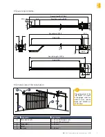
Страница 37: ... Aerial D Key lock 2 x 0 5 mm Overall length 3154 6 Mounting 2981 7 Rail 2900 Rail 2900 Overall length 3127 6 Working stroke 2555 140 Min 171 63 7 125 65 173 173 113 5 114 269 7 119 6 33 5 152 7 147 1 113 5 269 7 86 5 173 if the garage door is the sole means of access to the garage install an external back release device ref 2400658 or ref 9012962 L General view of the installation L Space require...

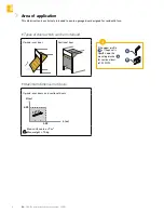
Страница 38: ...or designed for residential use Up and over doors and sectional doors 2 35 H m L m 3 00 2 90 m Max surface area 7 m2 Max weight 70 kg Maximum dimension of doors Up and over door Sectional door Types of doors which can be motorised If the upper profile A of the panel is specific use the mounting bracket B for sectional door ref 9009390 A B ...

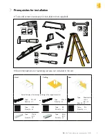
Страница 39: ...ty x 2 or Type M8 x 30 Quantity x 2 Type Sheet metal screw Ø 6 x 30 Quantity x 4 Type Ø 8 Quantity x 2 Type Ø 8 Quantity x 2 Type Ø 6 Quantity x 4 Type Plastic Ø 10 Quantity x 2 Type Steel Ø 10 Quantity x 2 E Recommendations for fastening screws not included in the kit E Tools and screws necessary for installation not supplied Ø 10 mm Béton Acier PZ2 3 5 Ø 3 mm 17 10 13 Concrete Concrete ...

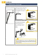
Страница 40: ... 200 Case 2 Motorisation not against ceiling If D is greater than 200 mm secure the assembly so that the height H is between 10 and 200 mm H distance between the bottom of the rail and the highest point of the door When installing centre the assembly in relation to the garage door D 200 10 H 200 To facilitate taking dimensions on the lintel once D has been measured determine H by subtracting 10 fr...

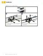
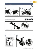
Страница 41: ...to the lintel or directly to the ceiling Centre the door bracket in relation to the top of the door Attach the bracket 1 EN Installation Fastening the lintel and door brackets 8 Case 1 Motorisation against ceiling To optimise the motor travel offset the bracket by max 200 mm in relation to the lintel 200 mm max Ø8 x 50 C C Ø8 x 50 Ø6 x 30 Ø6 x 30 D ...

Страница 42: ...Y EN 1 Installation C 1 2 Ø8 x 50 Ø6 x 30 Ø6 x 30 Centre the lintel bracket in relation to the garage door Attach the bracket Centre the door bracket in relation to the top of the door Attach the bracket D D C 5 Case 2 Motorisation not against ceiling ...

Страница 43: ... the sections Check that the belt on the inside of the rail is not twisted Assembling the rail in 3 sections 3 Case 1 Motorisation against ceiling Case 2 Motorisation not against ceiling x 16 In the case of a motorisation attached to the ceiling do not use the sleeve mounting screws Secure the assembly using the mounting screws The mounting screws must not penetrate the rail do not drill 1 2 Assem...

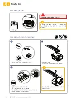
Страница 44: ...op at the end of the rail Standard assembly Fit the motor sha into the pinion of the rail 3 Assembly of the motor head at 90 to optimise the motor travel X Tighten the nut to tauten the belt The rubber squashes when tightened To obtain the correct tension the rubber must measure between 18 and 20 mm distance X To fasten the bulb position the motor flat Press firmly on the bulb to insert it into its ...

Страница 45: ...rail to the ceiling Fastening the unit to the ceiling 0 Case 1 Motorisation against ceiling 1 2 h 255 mm N L F E Fasten the unit at the motor head 0 Case 2 Motorisation not against ceiling 1 2 Position the assembly in the lintel bracket by placing the motor head on the ground or the on cross member Fasten the assembly to the lintel bracket N M ...

Страница 46: ...0 mm and 550 mm use the ceiling mounting kit ref 9014462 3 4 N L Ø8 x 50 1 2 3 G O P H O P Release the carriage using the manual back release device Bring the carriage level with the door Secure the arm to the door bracket and carriage If the back release handle is higher than 1 80 m it will be necessary to extend the cable to make it accessible to all users Fastening the link arm to the door and ...

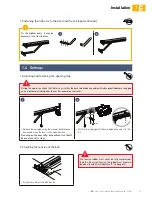
Страница 47: ...he manual back release device and move the door to the open position Do not open the door fully but position it so that it does not reach its stops Position the stop against the carriage and secure it to the rail 1 2 1 4 Settings Adjusting and fastening the opening stop If necessary adjust the belt tension The tension rubber must never be fully compressed to obtain the correct tension the rubber m...

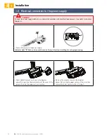
Страница 48: ...6 Assembling disassembling the cover Reassemble the cover as shown in the diagram above first position the lower section of the cover in the groove then clip the upper section into place Remove the cover as shown in the diagram above first unclip the upper section of the cover then remove the lower section without forcing it Connect the power supply cable to a socket which complies with electrical...

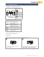
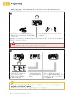
Страница 49: ...ess button B to enter auto programming mode Indicator light B flashes twice continuously the motorisation is waiting for auto programming 2 specific cases A Case 1 No indicator light flashes auto programming mode must be selected Functions of buttons and indicator lights Button A Using forced operating mode Selecting a setting Button B Triggers auto programming Memorising clearing the remote contro...

Страница 50: ...tle moves in the opposite direction to the previous movement Release button A before the motor exerts too much pressure on the door 4 x 2 x 2 Press button B to launch the auto programming cycle The door performs a complete Opening Closing cycle If the auto programming is correct indicator light B goes out If the auto programming cycle was not successful indicator light B flashes twice In this case ...

Страница 51: ... below Press button B to change the value of the parameter The programming procedures below must only be followed if you want to change the default value of the parameters Indicator light A Obstacle detection sensitivity Indicator light B very low sensitivity low sensitivity Standard default value high sensitivity At the end of installation it is essential to check that the obstacle detection comp...

Страница 52: ...s the value of the parameter see table below Press button B to change the value of the parameter Choice of type of power supply Indicator light A Power supply type Indicator light B Mains power supply default type of power supply Solar power 1 2 x 5 N x 5 N Press button A repeatedly until indicator light A flashes five times Type of power supply mode is activated The number of times N that indicator...

Страница 53: ...ess button A repeatedly until indicator light A flashes four times Parameter menu locking mode is activated Press button B once Indicator light A goes out The parameters menu is locked At this stage in the installation the motorisation is operational The remote controls supplied in the kit have already been memorised Parameter programming is now complete the parameters menu must always be locked to...

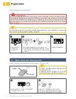
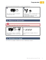
Страница 54: ... carried out using a button which has already been memorised the button will be cleared 1 2 2 s 5 s Press button B for 2 seconds The integrated lighting comes on Press the button on the remote control The integrated lighting flashes for 5 seconds The remote control button has been memorised F Memorising the remote controls for operation in Total opening mode Button 1 Button 2 The keypad for setting...

Страница 55: ... control has been memorised Memorising a Telis type remote control or similar not supplied in the kit 7 s 5 s 7 s Press button B for 7 seconds The integrated lighting comes on then begins to flash 5 seconds All the remote controls and all the settings are now cleared 2 5 Clearing the remote controls 2 6 Reinitialising the settings This procedure causes all memorised remote controls to be cleared To...

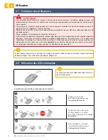
Страница 56: ...tion applying all the recommendations in this manual It is essential to ensure that no untrained persons are able to put the door into motion The user must monitor the door as it moves and keep people away from it until the door is completely open or closed Do not allow children to play with the door control devices Keep remote controls out of the reach of children Do not deliberately prevent the ...

Страница 57: ... causes the door to stop 3 Pressing the remote control button causes the door to open 1 Pressing the arrow up button causes the door to open 2 Pressing the central remote control button when the door is opening or closing causes the door to stop 3 Pressing the arrow down button causes the door to close Using the remote control with door open Using a 3 button remote control 3 EN Operation ...

Страница 58: ...ction operates up to 5 cm from the ground It is intrinsic to the motorisation and operates without any accessories photoelectric cells The integrated lighting comes on each time the motorisation is switched on When the door stops moving it goes off automatically aAer 30 seconds 3 4 Integrated lighting operation Repetitive use will cause the integrated lighting to be lit constantly which may result ...

Страница 59: ...motorisation by moving the door manually until the motorisation mechanism re locks on the transmission rail Following a power outage the motorisation must recognise its fully open position again Open the door fully using a memorised remote control The door will open at a reduced speed Allow the door to open to its fully open position When releasing the motorisation an incorrect balance may result ...

Страница 60: ...2 of the motor electronics EN 4 Accessories The photoelectric cells allow the presence of an obstacle to be detected when opening closing the door An obstacle placed between the cells will prevent the door from closing if an obstacle is detected when the door is closing the door stops then reopens The integrated lighting is activated intermittently for 30 seconds The orange light is activated when...

Страница 61: ...orisation will work even during a general power outage Operation is then activated under the following conditions Reduced speed The lighting does not work the safety devices are inactive Battery specifications Battery life 24 hours 5 to 10 operating cycles depending on the weight of the door Recharging time 72 hours Service life before replacement Approximately 3 years For optimum battery life it ...

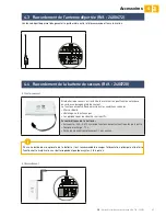
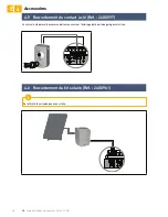
Страница 62: ...ng guide SOMFY EN 4 Accessories 4 5 Connecting the key contact Ref 2400597 4 6 Connecting the solar kit Ref 2400961 6 5 7 The key contact serves to control the moving and lighting of the motorised garage door Refer to the solar panel guide ...

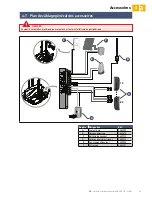
Страница 63: ...ing diagram Switch the electrical power supply to the motorisation off before installing any peripheral C A TX RX B D Mark Designation Ref A Key lock 2400597 B Offset aerial 2400472 C Backup battery 2400720 D Photoelectric cells 2400939 E Flashing orange light 2400596 F Solar kit 2400961 E F DANGER ...

Страница 64: ...vice Leave the motor to cool until the fault disappears 6 Motor current measuring circuit fault or sensor fault Switch off the power supply mains and backup battery wait a few minutes then reconnect the power supply Perform an auto programming cycle If the fault persists contact Somfy technical support 7 Maximum power delivered by the motor reached during the auto programming phase Product has rea...

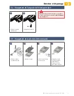
Страница 65: ...ace the bulb Handle the bulb with gloves or a cloth Only use a 24 V bulb max 20 W G4 halogen 5 5 Changing the remote control battery 1 2 3 4 3V CR 2430 3V CR 2430 3V CR 2430 Remove the clip from the remote control Li the cover Remove the battery using a screwdriver Replace the battery 3 V CR 2430 then reposition the cover and the clip of the remote control ...

Страница 66: ...X photoelectric cells Wired control input Dry contact NO Orange light output Flashing output for orange light 24 V 15 W Accessories power supply output 24 V 500 mA max Offset aerial input Yes RTS antenna compatible part no 2400472 Backup battery input Yes battery pack compatible part no 2400720 Battery life 24 hours 5 to 10 cycles depending on the door Recharging time 72 hours Operation Forced oper...

Страница 67: ......

Страница 68: ...somfy de Somfy LLC Russia 8 800 555 60 70 www somfy ru diy Somfy Nederland B V 023 56 23 752 www somfy nl Somfy Belux NV 02 712 07 70 www somfy be Somfy Ltd 44 0113 391 3030 www somfy co uk Somfy Sp z o o 810377199 www somfy pl Somfy España SA 900 20 68 68 www somfy es Somfy Portugal 808100153 www somfy pt Somfy Hellas SA 211 6000 222 www somfy gr Somfy Italia SRL 800827151 www somfy it ...

Отзывы: