3.2.1 INPUT STATUS
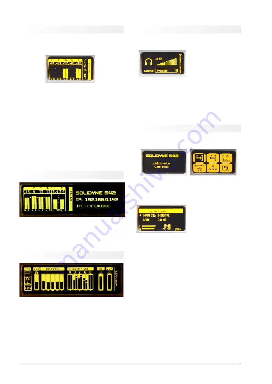
The screen INPUT shows the signal level on each audio in-
put. The
active input is indicated by an ARROW next to the
number
. By default the active input is the analogue XLR.
Figure 5: Inputs
3.2.1.1 INPUT SELECTION (from the frontal panel)
✔
Turn the wheel until see the screen INPUT.
✔
Press the wheel to change the current active input.
✔
Turn the wheel to select an input (number and name
of the input is shown at right eg: "2: ANALOG2").
✔
Press the wheel to confirm an option.
✔
The new active input is indicated by an arrow next to
the number.
✔
The last step is the gain adjustment, explained later
in the SETUP screen.
3.2.2 OUTPUT STATUS
Figure
6: Outputs
Shows the audio level at each output. From the frontal
panel, the output settings are in the SETUP screen. The
procedure to change the output gain is like the explained
above for the inputs.
3.2.3 PROCESSING MONITOR
Figure 7: Processing
It shows the action of the AGC, multiband AGC, the multi-
band compressor, multiband limiter, clipers, wideband lim-
iter and final clipper.
The audio processing settings can be edited only access-
ing with an external computer to the 542’s web interface.
3.2.4 Headphones
It adjusts the level for the headphone output. The user can
choose the audio source between the following signals:
•
Audio input.
•
FM tuner.
•
AGC output.
•
Audio processed (de-em-
phasized).
•
To choose an audio source, push the wheel and ro-
tate to navigate the options. Push again to confirm.
•
To leave the screen HEADPHONES,
press and hold
the wheel
until see a menu with alternating op-
tions. Release the wheel on BACK to return, or
SETUP to go to SETUP screen.
3.2.5 SETUP
To access to settings options, press the wheel on the
screen SETUP MENU:
Figure 9: Settings
The basic settings are:
3.2.1.2 INPUT GAIN
The inputs gain is set on the-
screen SETUP
INPUT
→
CONFIG. Gain control works
in a range of +/- 14dB. The
gain for the analog inputs is
refered to -18dBfs for nomi-
nal input level of +4dBu (AES
K18). It represents a head-
room of 18dB.
To adjust the level, the on-air mixing console must
peaking at 0VU with audio program (i.e. music). Set
the input gain in order to the peaks in the level me-
ter of the 542APC moves between -22 and -9 dBfs.
✔
Turn the jog wheel until see the screen "enter SETUP
MENU" and push the wheel to enter.
✔
Turn the wheel to select "IN" and press it to access to
INPUT CONFIG.
✔
Press the wheel to select "INPUT SEL". Turn the
wheel until see the desired input and press to con-
firm.
✔
Select "GAIN" by turning the wheel and press to edit
the gain value.
✔
Turn the wheel clockwise to increase the gain and
counterclockwise to decrease it. As was explained
above, the gain adjusts so that the level indicators
peaking moves between -22 and -9 dBFS.
✔
Press the wheel to confirm the gain.
Page 16
Audio Processing Core -
SOLIDYNE 542
APC
Figure 10: Setup input gain
Figure 8: Headphones level
Содержание 542 APC
Страница 1: ......
Страница 2: ...Page 2 Audio Processing Core SOLIDYNE 542APC...
Страница 6: ...Page 6 Audio Processing Core SOLIDYNE 542APC...
Страница 10: ...Page 10 Audio Processing Core SOLIDYNE 542APC...
Страница 30: ...Page 30 Audio Processing Core SOLIDYNE 542APC...
Страница 42: ...Page 42 Audio Processing Core SOLIDYNE 542APC...


