PVI 1800/PVI 2500
Installation and Operation Manual
43
Appendices
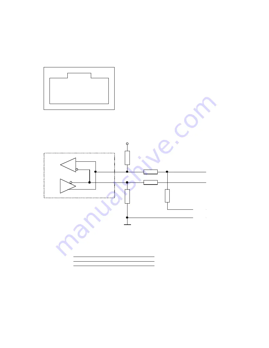
Appendix A: Terminal assignment RS-485 / RS-232
:
Pin
1
Not used
2
RXD (RS232)
3
TXD (RS232)
4
GND (RS232/RS485)
5
TERM (RS485)
6
RX_B (RS485)
7
TX_A (RS485)
8
Not used
8
1
Top view
Hint!
Both RJ45 connectors have the same pinout.
+5V
0R
Not
used
Not
used
0R
TX_A
RX_B
TERM
GND
Representative RS485 schematic, inside the inverter
Pin
3 - TD
2 - RD
5 - GND
RS232 9pol.
Pin
2 - RXD
3 - TXD
4 - GND
RJ45 (inverter)
RS 232 cable (schematic)
121R
Содержание PVI 1800
Страница 12: ...PVI 1800 PVI 2500 Installation and Operation Manual 12 Fig 4 PVI 1800 PVI 2500 Dimensional Diagram ...
Страница 47: ...PVI 1800 PVI 2500 Installation and Operation Manual 47 Appendix E UL1741 Certification ...
Страница 48: ...PVI 1800 PVI 2500 Installation and Operation Manual 48 ...
Страница 49: ...PVI 1800 PVI 2500 Installation and Operation Manual 49 Appendix F Letter of Attestation IEEE C62 41 2002 ...


