PVI 1800/PVI 2500
Installation and Operation Manual
14
NOTE:
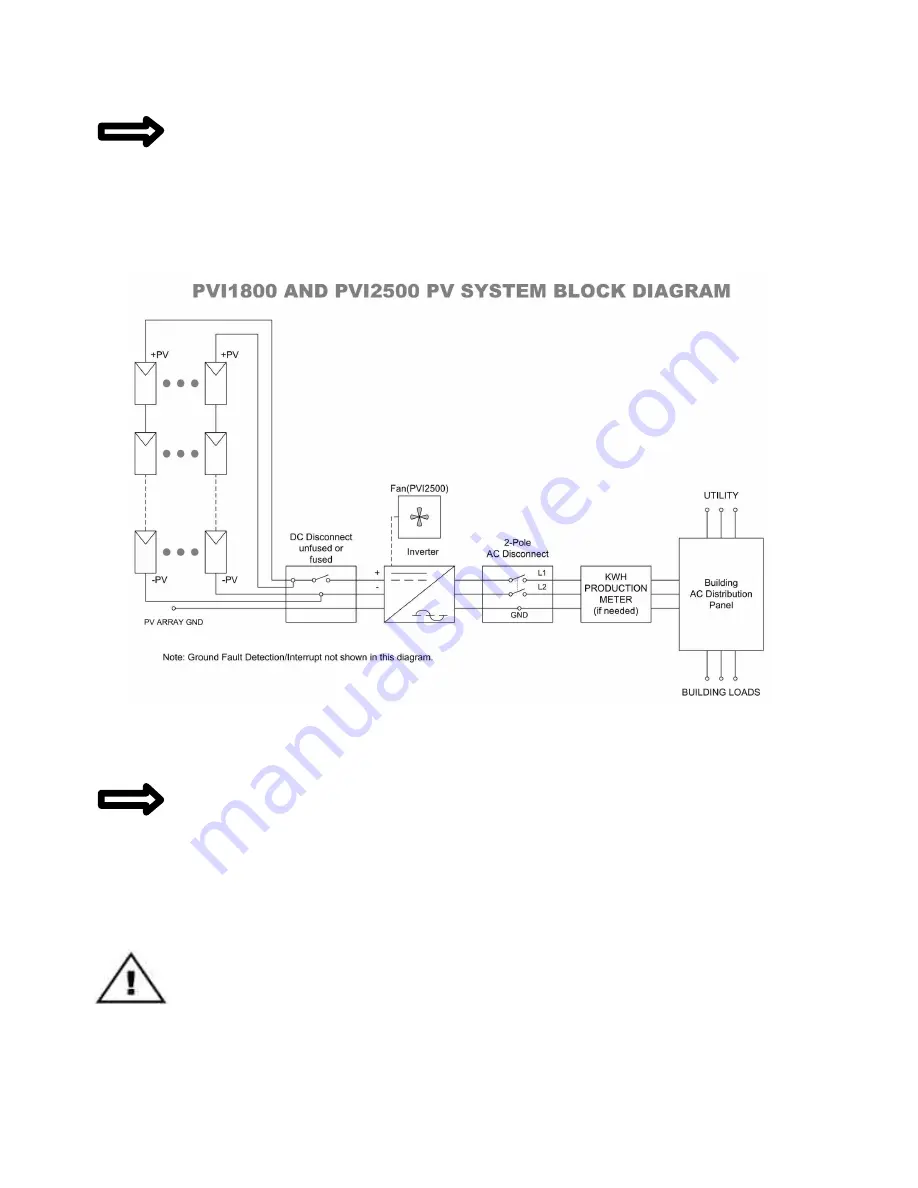
The inverter is set up with pre-wired AC and DC connections to make it very easy
and quick to connect to a DC disconnect to the left of the inverter and an AC disconnect to
the right. (Connections can also be made to junction boxes.)
2.3 Electrical Connection and Connection To Electrical
Utility Grid
Fig. 6 Simplified electrical connection diagram
Location and Mounting the Inverter
NOTE:
Choose the inverter location keeping in mind where the disconnects, and/or
junction boxes and kWh meter (if needed) will be located. It is best to mark
on the wall
(or create a diagram) where all of the components are to be located. The inverter is set up
with pre-w ired AC and DC connections to make it very easy and quick to connect to a
DC disconnect to the le ft of the inverter and an AC disconnect to the right.
Refer to Figure 2 for Locations of Features, AC and DC Wires, etc.
WARNING:
All electrical installations shall be done in accordance with all local electrical
codes and the National Electrical Code (NEC), ANSI/NFPA 70.
Содержание PVI 1800
Страница 12: ...PVI 1800 PVI 2500 Installation and Operation Manual 12 Fig 4 PVI 1800 PVI 2500 Dimensional Diagram ...
Страница 47: ...PVI 1800 PVI 2500 Installation and Operation Manual 47 Appendix E UL1741 Certification ...
Страница 48: ...PVI 1800 PVI 2500 Installation and Operation Manual 48 ...
Страница 49: ...PVI 1800 PVI 2500 Installation and Operation Manual 49 Appendix F Letter of Attestation IEEE C62 41 2002 ...


