PVI 1800/PVI 2500
Installation and Operation Manual
11
•
The ambient temperature must be between
– 4
o
F (– 20
o
C) and +131
o
F (+ 55
o
C) for full continuous,
full power operation. (The inverter will automatically reduce power or shut down to protect itself if
the ambient air temperature rises above 131
o
F (55
o
C).)
•
The National Electrical Code (NEC) requires that the inverter be connected to a dedicated AC circuit
and no other AC outlets or device may be connected to this circuit. See NEC Section 690.64. The
NEC also imposes limitations on the size of the inverter and the manner in with it is connected to the
utility grid. See NEC Section 690.64.
•
The cooling air enters at the bottom and exhausts at the top of the unit.
•
A minimum distance of 6 inches (152mm) must be clear above and below the inverter for ventilation.
•
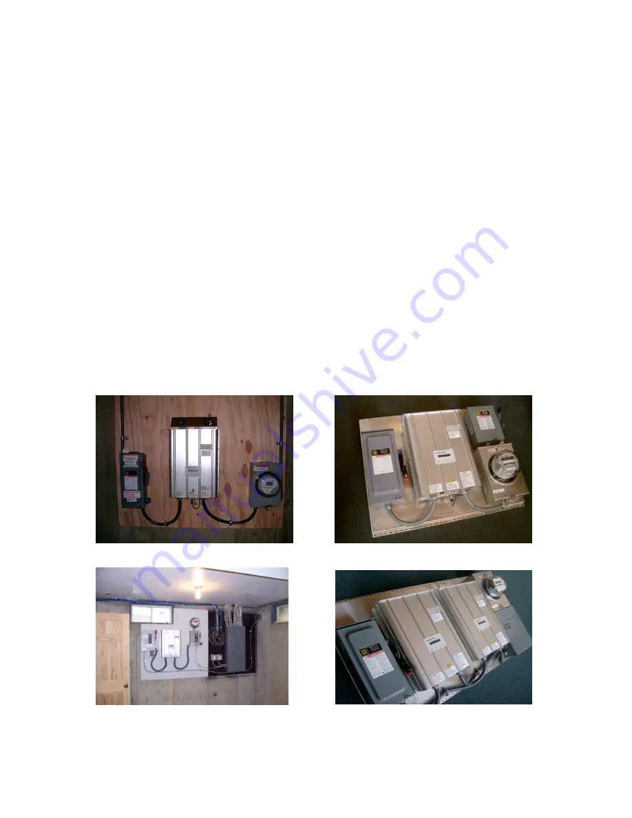
The inverter must be mounted directly on a flat (wall) surface. (Do not mount to open studs or any
horizontal or vertical beams or struts as this can hinder proper cooling performance). The inverter
must be mounted vertically (see mounting photos).
•
If you are installing the inverter in a utility vault or electrical closet, the air circulation must be
sufficient for heat dissipation – provide external ventilation, to maintain an ambient condition of less
than 131
o
F (55
o
C). The ambient temperature should be kept as low as possible.
•
See photo and use dimensional diagrams for correct mounting of the inverter.
Painted plywood board in basement (BPVS)
Typical mounting on plywood board (Sunlight Solar)
Optional panel assembly available
Fig. 3
How to mount the inverter
Optional double panel assembly available
Содержание PVI 1800
Страница 12: ...PVI 1800 PVI 2500 Installation and Operation Manual 12 Fig 4 PVI 1800 PVI 2500 Dimensional Diagram ...
Страница 47: ...PVI 1800 PVI 2500 Installation and Operation Manual 47 Appendix E UL1741 Certification ...
Страница 48: ...PVI 1800 PVI 2500 Installation and Operation Manual 48 ...
Страница 49: ...PVI 1800 PVI 2500 Installation and Operation Manual 49 Appendix F Letter of Attestation IEEE C62 41 2002 ...


