TIGHTENING TORQUES
50
Manual del Operador Grupos Electrógenos Marinos
Revisión 2. 10/2017
OPERATION
This genset can be operated with or without our Parallel Kit. So if you
have installed this kit, see the Parallel Kit Manual to operate the genset.
On the other hand, if it has not been installed, you have to design the
control part of the genset. For this reason, it is necessary take into account the
requirements of the electrical wiring, according to the ECU cabinet connector,
where you have to connect.
Connect
or
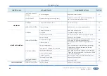
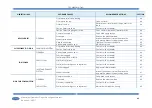
SPECIFICATIONS
PIN
IDENTIFICATION
DESCRIPTION
I/O SIGNAL*
SIGNAL
REQUIREMENTS
1 Spare
Not used
-
White
2 Spare
Not used
-
Grey
3 Spare
Not used
-
Green
4 CAN low
CAN-interface SAE J 1939:
ECU-Controller communication while ECU
is activated.
Input/Output
CANL
Blue
5 CAN high
Input/Output
CANH
Brown
6 Screen
Input/Output
Earth point
White
7 Cranking signal
Cranking relay excitation:
This signal closes the cranking relay switch
in order to engage the starter motor.
*The start sequence should finish when
the genset exceeds value of 25% nominal
speed.
Input
24 VDC
Pink
8 ECU power signal
Power supply signal:
It has to be always active.
Input
24 VDC
Yellow
9 +5Vref Speed governor
Engine speed control:
Regulation used to correct the genset
speed in order to mantain 1500 rpm (50
Hz) or 1800 rpm (60Hz).
U
in
= 0.5-4.5 VDC, f
g
= 7 Hz, R
i
= 220 kΩ,
U
ref
= 5 VDC ± 25 mV, I
max
= 25 mA
Input
5.0 VDC
Blue
10
Voltage speed governor
signal
Input
0.5-4.5 VDC
Brown
11 GND Speed governor
Input
GND
Yellow-Green
12 Screen
Input
Cut on its end
White
13 D+
DC Alternator excitation:
Excitation used to begin the current
generation.
Input
200 mA / 24
VDC
Red-White
14 B
Power supply for the controller:
Power output available for the controller.
Output
24 VDC
Red
15 Battery -
Output
Black
16
AVR remote voltage
control signal
Voltage control (AC alternator):
Regulation used to correct the genset
output voltage.
U
in
= 0.0-2.5 VDC or 10K Potentiometer
Input
0-2.5 VDC
Blue
17 AVR common
Input
GND
Brown
18 Screen
Input
Earth point
White
19 Emergency Stop signal
This signal open cranking and ECU relays
in order to stop engine
Input
24 VDC
Purple
20 Spare
Not used
-
21 Spare
Not used
-
22 Spare
Not used
-
23 Spare
Not used
-
24 Spare
Not used
-
Input: signal from the controller to ECU cabinet.
Output: signal to the controller from ECU cabinet.
Содержание 100 GTA
Страница 1: ...U_GNBL_EN Rev 2 ...
Страница 2: ...INTRODUCCION 2 Operator s Manual Marine Diesel Gensets Revision 2 10 2017 ...
Страница 49: ...ELECTRICAL DIAGRAMS 49 Manual del Operador Grupos Electrógenos Marinos Revisión 2 10 2017 10 1 Wiring diagrams ...
Страница 56: ......
Страница 58: ......
Страница 66: ......
Страница 67: ......
Страница 68: ......
Страница 69: ......
Страница 70: ......
Страница 75: ......
Страница 76: ...MAINTENANCE LOG 75 Manual del Operador Grupos Electrógenos Marinos Revisión 2 10 2017 U_GNBL_EN Rev 2 ...

