8 Electrical connection
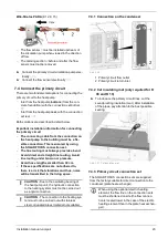
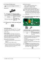
8.7.5 Connect the flow sensor
i
Only required for
vamp
air
K 12 and K 15.
Flow sensor
►
Connect sensor to the electronic module D1
Sensor
Electronic module
Return temperature sensor
(PT1000)
i4
, white and grey wire,
polarity can be swap-
ped
Flow sensor (flow volume)
brown:
i15
- 24V
black: i15
- earthing
blue: i15
- I
8.7.6 Heating circuit - switch externally (optio-
nal)
Function Description
This function of the control
eco
manager-
touch
enables
the switching on/off of the heating circuit by a swit-
ching contact.
Usage example
As soon as all room thermostats (of a single room
control) have reached the required temperature, the
control receives
eco
manager-
touch
a signal, and the
heating circuit is switched off. When the temperature
drops, the heating circuit is switched on again.
Prerequisite for functionality
–
The parameter
Room effect
[1]
must be set to the
option
On
.
–
Software version 19.020 for control
[1] You can find the parameter
Room effect
in the heating circuit
settings of the control: Screen
Heating circuit
| Screen
System
parameters
.
To ensure visibility of the parameter, registration
with qualified personnel code is required
.
Electrical connection
–
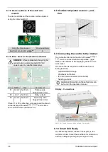
Input
i1
on electronic module
D1
(=D1i1)
–
Contact closed = heating circuit
On
Contact open = heating circuit
Off
–
Switching contact must be potential-free
i
When using the optional item 26100 (
exten-
sion of buffer operation with a mixed heating
circuit
) the room thermostats on are connec-
ted to X40 and X41 of the heating circuit basic
module. The connection
D1i1
has no function
in this case.
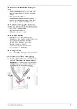
8.7.7 Connecting the mains power supply to
the electronic module
Mains power supply
Electronic module
L
X1
– L
N
X1
- neutral conductor N
PE
X1
– protective earth con-
ductor PE
–
Establish the connection to a standard protective
contact plug so that the electronic module can be
disconnected from the power supply as
necessary.
–
For the 230 V AC supply use a 3 x 1.5 mm² cable
(protection with 10 A fuse B).
–
Comply with regulations of the regional electrical
utility firm.
!
CAUTION
- Connect the
PE
blade terminal
(6.3 x 0.8 mm) of the electronic module to the
potential equalisation in the building instal-
lation (cable cross-section ≥2.5 mm²).
Installation manual
vampair
35
Содержание Vampair
Страница 31: ...8 Electrical connection Installation manual vampair 31 8 5 Electrical connection plan ...
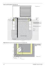
Страница 39: ...10 Foundation plan Installation manual vampair 39 Side view of foundation Section A A Abb 2 48 ...
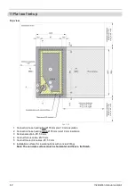
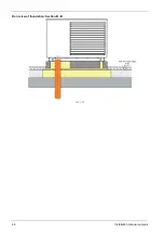
Страница 44: ...Front view of foundation Section B B Abb 2 55 11 Flat roof set up 44 Installation manual vampair ...
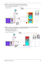
Страница 51: ...12 Plant schematic Installation manual vampair 51 ...


