8 Electrical connection
8.6 Connect eco
manager-
touch
control
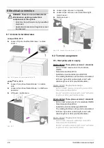
Mount the control (display with metal surface-
mounted housing) and the electronic module on the
wall inside the building (e.g. in the equipment room).
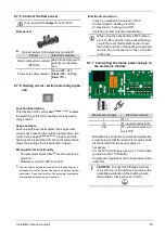
8.6.1 Overview
Interfaces on the display
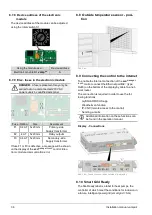
8.6.2 Surface-mounted installation
►
It is possible to install the metal housing with 4
boreholes
1
.
►
Installation on electrical flush-mounted socket is
possible with boreholes
2
.
(screw materials for installation of housing not inclu-
ded in scope of delivery).
►
Install the power supply in the housing.
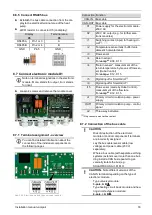
8.6.3 Display power supply
►
Run the power supply for the display from the
power supply unit (supplied).
Display
X1
Power supply unit
+ 24 V DC
Pin 1 or 2
+
GND
Pin 3 or 4
-
8.6.4 Connect CAN bus
►
Make bus cable connection from the display to
the electronic module D1.
Display
X4
Electronic module
CAN-IN
CAN A
Pin 1 or 3
A
CAN B
Pin 2 or 4
B
GND
Pin 5
GND
⏊
32
Installation manual
vampair
Содержание Vampair
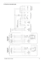
Страница 31: ...8 Electrical connection Installation manual vampair 31 8 5 Electrical connection plan ...
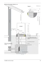
Страница 39: ...10 Foundation plan Installation manual vampair 39 Side view of foundation Section A A Abb 2 48 ...
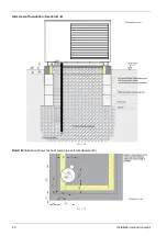
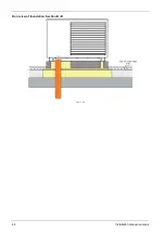
Страница 44: ...Front view of foundation Section B B Abb 2 55 11 Flat roof set up 44 Installation manual vampair ...
Страница 51: ...12 Plant schematic Installation manual vampair 51 ...

