Chapter 5: LCD
–
Status Screens and Setup Options
Control and Communication Gateway Installation Guide - MAN-01-00132-1.2
39
Power Control
For detailed information about power reduction control connection and configuration, refer to the Power
Reduction Control application note, available on the SolarEdge website
http://www.solaredge.com/files/pdfs/power-reduction-control-application-note.pdf
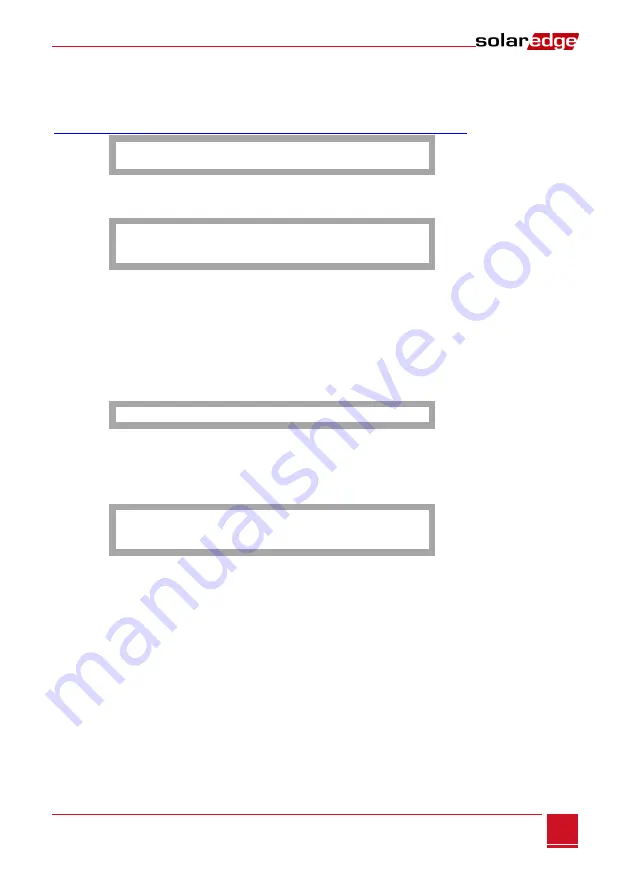
R R C R C o n f .
L o a d D e f a u l t s
Sensors
Select
Sensors
to set the following options:
V 1 S e n s o r < D i s >
V 2 S e n s o r < D i s >
I S e n s o r < D i s >
The SolarEdge gateway sensor interface supports up to three analog sensors:
V1, V2
: Voltage sensors
I
: Current sensors
For detailed information about all the configuration options for sensors, refer to
Environmental Sensors (Optional)
Display
Select
Display
to set the following:
L C D O n T i m e < 3 0 >
LCD On Time
<30>
: The number of seconds that the LCD backlight is ON after the LCD button is
pressed.
Maintenance
Select
Maintenance
to set the following options:
D a t e a n d T i m e
F a c t o r y R e s e t
S W U p g r a d e S D C a r d
Date and Time
: Set the internal real-time clock. If connected to the SolarEdge monitoring portal, the
date and time are set automatically and only time zone should be set.
Factory Reset
: Perform a general reset to the gateway default settings.
SW Upgrade SD Card
: Perform a software upgrade using an SD card.


