UPS for 400 Vac Grid, Installation Guide, doc. rel. 3.0
79
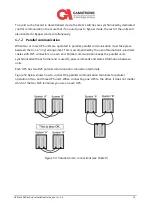
Figure 55:
Common DC
Parallel communication cable
Figure 56:
Decentralized DC
Parallel communication cable
4.
Verify that each UPS’s output circuit breaker is in the OFF position
(CB5 in the
connection diagrams - Figure 60).
5.
Turn on one of the systems. This system will become the “master” system. Wait until the
startup procedure is complete
–
you will see the System Menu.
Содержание Gamatronic B300
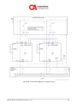
Страница 91: ...UPS for 400 Vac Grid Installation Guide doc rel 3 0 83 Figure 60 Connection diagram for 2 parallel units ...
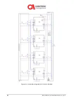
Страница 92: ...84 UPS for 400 Vac Grid Installation Guide doc rel 3 0 Figure 61 Connection diagram for 4 Units in Parallel ...
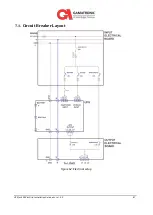
Страница 95: ...UPS for 400 Vac Grid Installation Guide doc rel 3 0 87 7 1 Circuit Breaker Layout Figure 62 Electrical setup ...


