December 2020
|
Solar Stik
®
, Inc.
30
|
System Setup and Operation Manual for the Solar Stik G-BOSS E Light HPS
PRELIMINARY
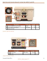
PRO-Verter Faceplate
Generator
Control
Switches
Generator Type
Switch
AGS Tech Port
AGS Alarm
and Alarm-
defeat Switch
User Interface
Navigation
Buttons
PRO-Verter
Status and
Alarm LEDs
User Interface
Power Button
System
Recovery
Switch
Input, Output and Internal
Component Breakers
PRO-Verter
Specs
USB Charging Port
User Interface
– The user interface is used to program and control the PRO-Verter and to monitor
System status. The PRO-Verter is programmed at Solar Stik to meet the specifications of a specific
application. Programming mode can be accessed if reprogramming is required. Contact Solar Stik
Technical Support.
System Recovery Switch
– Provides a method to start the PRO-Verter when the System batteries
have been overdischarged. Connect the PRO-Verter to a 120 VAC power source. Press and hold
the System Recovery button. Turn on the PRO-verter user interface. Continue pressing the System
Recovery button until the user interface reports “Charging”.
Generator Type Selection Switch –
Choose “RANGER/DEFENDER” if the PRO-Verter is connected
to either of these gensets. Choose “OTHER” if connected to other gensets (e.g., MEP-802A or MEP-
831A) that have been equipped with auto start/stop functionality. \
Auto Generator Start/Stop (AGS) Switches
– The “ON” position manually turns on a generator;
the “AUTO” position automatically starts and stops the connected generator based on programmed,
battery voltage values. The “OFF” position defeats AGS communication with any connected genset.
AGS Alarm and Defeat Switch –
Audible indication that a connected generator is in the process of
starting. Alarm may be defeated (toggle switch) when silent operation is required.
Figure 22. PRO-Verter Faceplate features


