Title: MAN 266, GTecLink Data loggers User Manual
Rev 1.0.1
Page 5 of 32
d.
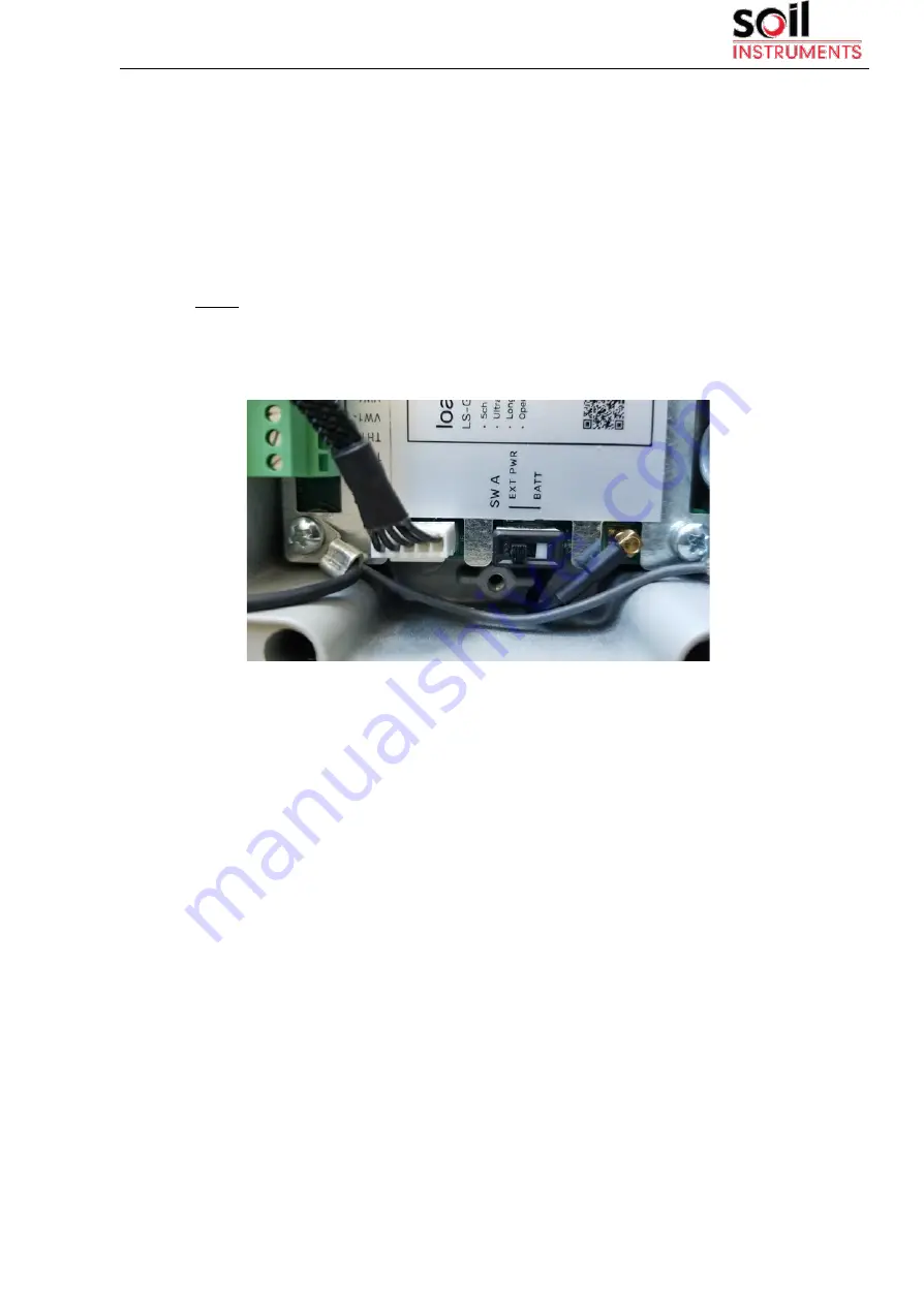
Check that power switch (SW A, Figure 3) is in the correct position.
USB: the data logger is powered by the USB cable connected to any
Android device or an external power source
BATT (default): the data logger is powered by the batteries.
Note: Some Android devices cannot power the data logger, especially
when performing a reading. If reading fails, set the switch to BATT
mode in order to power the data logger with batteries.
Figure 3: Detail of
power switch (SW A)
2.3 Connecting Sensors
Sensors are connected to the data logger at the terminal blocks.
Each terminal block corresponds to one channel of the data logger.
The terminal blocks accept wires that are prepared by stripping a short
length of insulation from the end.
Each data logger type has specific instructions for sensor wiring.
Specifications for each model can be found i n the following sections:
3.1. (Vibrating wire data loggers)
3.2. (Digital data loggers)
3.3. (Analog data logger).


