SET-UP INSTRUCTIONS & PRE-OPERATION CHECKLIST
SNAPPER LARGE FRAME ZERO TURNING Z-RIDER with MID MOUNT MOWER
INTRODUCTION: These instructions cover the set-up of the Snapper Large Frame Mid Mount Z-Rider Mower.
Complete each of the following steps carefully. Review and complete each item as instructed on the Pre-Operation
checklist. The Snapper Product Registration card must be filled out and sent to Customer Service department at
Snapper when completed.
IMPORTANT: The battery for this unit is maintenance-free. It is filled with acid and is sealed. Do not attempt to
open the battery. Pay close attention to the precautionary statements on the battery and in these instructions. If
charging is needed (see below), you will need an automotive type battery charger to activate the battery for use.
STEP 1:
Remove machine from the container.
STEP 2:
Assemble motion control levers:
A.
Carefully remove wire ties securing folded handles
to machine.
B.
Remove noted hardware from motion control lever
blocks. See Figure 1.
C.
Unfold motion control lever handles, and secure
with removed hardware. See Figure 1. Tighten all
hardware securely.
NOTE:
Motion control levers may require adjustment. Refer
to Operator’s Manual for adjustment procedures.
STEP 3:
Install seat:
A.
Check to make sure that there are two flat washers
installed onto each of the four seat mounting studs and
secured by a retaining ring. (If missing, replace with
three standard 5/16 flat washers.)
NOTE:
Seat must be in rearmost position during
installation. Refer to Operator’s manual for seat
adjustment procedures.
B.
Install seat to seat plate, and secure each stud with
one 5/16 flat washer and nyloc nut. See Figure 2.
Tighten securely.
NOTE:
Secure the harness clip to the left forward stud
before installing the washer and nut. Slip the harness
for the seat safety switch into this clip. See Figure 2.
STEP 4:
Install rain cap onto engine air cleaner assembly,
securing with supplied worm drive clamp. Tighten securely.
See Figure 3.
STEP 5:
Install roll bar protective structure:
A.
Install side bars into frame brackets behind fuel
tanks, making sure hinges on top of bars are facing
toward rear of machine, and safety decals are facing
forward and inward. See Figure 3. Secure each bar to
its corresponding bracket with two 1/2-13 x 4-1/2” hex
bolts and lock nuts. Do not tighten yet.
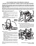
FIGURE 1
INSTRUCTION No. 7100719 (Rev. 1, 7/7/2006)
TP 300-5177-R1-HZ-N
1
FIGURE 2
UNFOLD
HANDLES
REMOVE &
REINSTALL
HARDWARE
HARNESS CLIP,
WASHER AND NUT
WASHER
AND NUT
FIGURE 3
SAFETY DECALS
FACING FORWARD
AND INWARD
ATTACH TO
FRAME
BRACKET
HINGES
FACING
REARWARD
ANTI-VIBRATION
BOLT
AIR CLEANER CAP
Содержание Zero Turning Z-Riding
Страница 5: ...NOTES 5...


