background image

20

Specifications & Notes

Torque Specification Chart

FOR 

S

TANDARD MACHINE HARDWARE (Tole

r

a

n

ce ± 20%)

Ha

rd

wa

r

e

G

r

a

d

e

SAE G

r

a

d

e 2

SAE G

r

a

d

e 5

SAE G

r

a

d

8

Size Of

i

n

/lb

s

i

n

/lb

s

i

n

/lbs

Ha

rd

wa

r

e

ft/lbs

Nm.

ft/lbs

Nm.

ft/lbs

Nm.

8-32

19

2.1

30

3.4

41

4.6

8-36

20

2.3

31

3.5

43

4.9

10-24

27

3.1

43

4.9

60

6.8

10-32

31

3.5

49

5.5

68

7.7

1/4-20

66

7.6

8

10.9

12

16.3

1/4-28

76

8.6

10

13.6

14

19.0

5/16-18

11

15.0

17

23.1

25

34.0

5/16-24

12

16.3

19

25.8

27

34.0

3/8-16

20

27.2

30

40.8

45

61.2

3/8-24

23

31.3

35

47.6

50

68.0

7/16-14

30

40.8

50

68.0

70

95.2

7/16-20

35

47.6

55

74.8

8

0

108.8

1/2-13

50

68.0

75

102.0

110

149.6

1/2-20

55

74.8

90

122.4

120

163.2

9/16-12

65

88.4

110

149.6

150

204.0

9/16-18

75

102.0

120

163.2

170

231.2

5/8-11

90

122.4

150

204.0

220

299.2

5/8-18

100

136

1

8

0

244.8

240

326.4

3/4-10

160

217.6

260

353.6

3

8

6

525.0

3/4-16

1

8

0

244.8

300

408.0

420

571.2

7/8-9

140

190.4

400

544.0

600

816.0

7/8-14

155

210.8

440

598.4

660

897.6

1-8

220

299.2

5

8

0

788.8

900

1,244.0

1-12

240

326.4

640

870.4

1,000

1,360.0

Hex Head Capscre

w

Hex 

Nu

t

Lock

w

asher

W

asher

Carriage Bolt

NOTES

1. These torque values are to be used for all hardware

excluding: locknuts, self-tapping screws, thread forming
screws, sheet metal screws and socket head setscrews.

2. Recommended seating torque values for locknuts:

a. for prevailing torque locknuts - use 65% of grade 5

torques.

b. for flange whizlock nuts and screws - use 135% of

grade 5 torques.

3. Unless otherwise noted on assembly drawings, all torque

values must meet this specification.

Hard

w

are Identification  

&

  Torque Specifications

Common Hardware Types

Screw, 1/2 x 2

Body

Diameter

Body

Length

Inside
Diameter

Nut, 1/2”

N

o

Marks

3/

8

” Bolt or Nut

W

rench—9/16”

3/

8

5/16” Bolt or Nut

W

rench—1/2”

5/16

1/4” Bolt or Nut

W

rench—7/16”

1/4

1/2” Bolt or Nut

W

rench—3/4”

1/2

DIA.

7/16
DIA.

7/16” Bolt or Nut

W

rench (Bolt)—5/

8

W

rench (

Nu

t)—11/16”

Wrench & Fastener Size Guide

Standard Hardware Sizing

When a washer or nut is identified as 

1/2”

, this is the

Nominal size, meaning the inside diameter is 1/2 inch; if a

second number is present it represent the 

threads per inch

When bolt or capscrew is identified as 

1/2 - 16 x 2”

, this

means the 

Nominal size, or body diameter is 1/2 inch; the

second number represents the 

threads per inch (16 in this

example, and the final number is the 

body length of the

bolt or screw (in this example 2 inches long).

The guides and ruler furnished below are designed to
help you select the appropriate hardware and tools.

0

1/4

3/4

1/2

1

1/4

3/4

1/2

2

1/4

3/4

1/2

3

1/4

3/4

1/2

4

Содержание 1694151

Страница 1: ...evision 04 Rev Date 06 2008 TP 100 2604 04 AT UV CAUTION Read and follow all instructions 36 Rotary Tiller Attachment for use with Conquest 1700 2700 Prestige 1800 2800 Snapper YT400 and GT500 Series...

Страница 2: ...nstructions are not followed The information is for your safety and it is important The safety decals below are on your product If any decals are lost or damaged replace them at once See your local de...

Страница 3: ...the Hitches 10 Install the Pulley Assemblies 11 Install the Rear Idler Pulley Assembly Select Models 11 Install the Lift Rod 12 Install the Tiller 13 Install the Belt 13 Adjustments 13 Operation 14 O...

Страница 4: ...on of the product s features and controls and maintenance information is included to help you get the most out of your equipment investment Be sure to completely read the Safety Rules and Information...

Страница 5: ...er if you are seated in the seat properly and follow all the rules in this book the unit is safe to operate Do not allow anyone near the equipment while it is running To help you the operator use this...

Страница 6: ...mended by the manufacturer 7 Always wear safety glasses or eye shields during operation or while performing an adjustment or repair to protect eye from foreign objects that may be thrown from the mach...

Страница 7: ...lace safety and instruction labels as necessary 6 Keep nuts and bolts tight and keep equipment in good condition 7 Never tamper with safety devices Check their proper operation regularly and make nece...

Страница 8: ...achment raised back position 2 Loosen the manual lift adjustment bolt A Figure 2 until the bolt can be slid out of the groove in the bulkhead 3 Remove the pin A Figure 3 securing the lift link D 4 Rem...

Страница 9: ...t Lock F Lift Lever G Locknut H Hair Pin Clip I Spacer J Lift Cam K Mower Hole Figure 4 Lift Components Tilling A Clevis Pin B 5 16 18 x 1 Capscrew Gr 5 C Washer D Lift Link New E Lift Lock F Lift Lev...

Страница 10: ...ts J 3 Secure the sides of the hitch support C using four 3 8 16 x 1 capscrews D and four 3 8 16 nylock nuts B D B A C C B E Figure 6 Rear Hitch Installation A 1 2 13 x 2 Capscrew B Washer C Spacer D...

Страница 11: ...haft C 3 Hook the slot D onto the tractor frame as shown in Figure 9 Figure 8 Front Idler Pulley Installation A Idler Pulley Assembly B Left Stub C Lift Assembly Cross shaft D Slot Figure 9 Front Idle...

Страница 12: ...ght stub at the end of the lift assembly cross shaft Secure with a clevis pin and hair pin clip see Figure 12 inset MANUAL LIFT MODELS ONLY 3 Mount the front bracket D Figure 11 to the frame using a 5...

Страница 13: ...tall the Belt 1 Remove the spring clip and pin securing the tiller belt cover Pivot the belt cover out of the way to allow access to the tiller pulleys 2 Install the belt on the rear pulley assembly C...

Страница 14: ...und in your tractor Operator s Manual If tractor does not pass the test do not operate the tractor See your authorized dealer Under no circumstances should you attempt to defeat the safety system To p...

Страница 15: ...NG To avoid serious injury perform maintenance on the tiller only when the engine is stopped parking brake is set and all moving parts have stopped Always remove the ignition key before beginning main...

Страница 16: ...the mowing position C 1 Manual Lift Models Switch the lift link from mowing position C Figure 20 to tilling position D 2 Attach the tiller to the rear hitch see Figure 19 3 Install the lift bracket A...

Страница 17: ...Threaded Rod Spring C Lift Rod A B C Figure 18 Lift Arm Extension A Lift Bracket A C D A B Figure 19 Tiller Assembly A Lift Bar B Upper Hitch C Hitch Arm D Lower Hitch Figure 20 Lift Link Positions N...

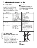
Страница 18: ...too hard 1 Adjust the attachment lift 2 Set engine to full speed 3 Slow down 4 Make several passes tilling deeper on each pass Tiller leaves ground rough with large clods 1 Ground too wet 2 Tilling to...

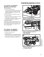
Страница 19: ...th of 9 WORKING ADJUSTMENT The amount of lift assist can be varied based on the depth of tilling and the hardness of the soil If more assist is desired the turn crank A Figure 24 clock wise If more do...

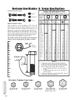
Страница 20: ...s self tapping screws thread forming screws sheet metal screws and socket head setscrews 2 Recommended seating torque values for locknuts a for prevailing torque locknuts use 65 of grade 5 torques b f...

Страница 21: ...21 Notes NOTES...

Страница 22: ...n com Briggs Stratton Power Products Group L L C Copyright 2008 Briggs Stratton Corporation Milwaukee WI USA All Rights Reserved www BRIGGSandSTRATTON com www MasseyLawn com www snapper com www simpli...

Отзывы: