


119
Information
Component Locations
9.4.2 Information Tabs
The Information Tabs determine how the ECM connector pin information displays. There are three
information options:
•
By Component—only the data for the selected component is shown in the table. Component
selections are listed by name only in alphabetical order, there are no pin numbers on the list.
•
By Pin Number—only the data for the selected pin is shown in the table. Component
selections are listed by pin number only in numerically ascending order, there are no
component descriptions on the list.
•
All Information—all of the available pin data displays in the table sorted alphabetically by
component name. A scroll bar at the right of the table is used to navigate through the data.
Use your finger or the stylus to select an information tab.
9.4.3 Component Selection
This field, which only displays when the By Component or By Pin Number tab is selected, is used
to select what data displays in the table.
z
To use component selection:
1. Select anywhere in the
Component Selection
field with the stylus.
The menu, sorted by component or pin as determined by the Information Tab selected, opens.
2. Select a menu item with the stylus.
The menu closes and the data for the selected item is now shown in the table. On the
connector diagram, the pin for the selected item appears in red.
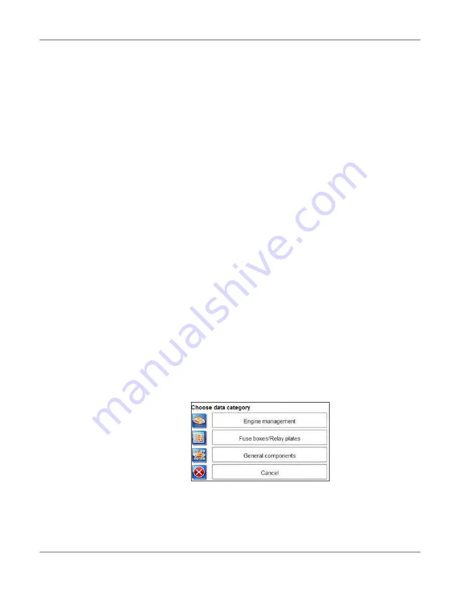
9.5 Component Locations
This section contains graphic depictions and textual references as to where specific components
are located on the test vehicle. Selecting the
Component Locations
icon on the home page
opens a data category menu.
Figure 9-8
Sample Component Locations category menu
The categories vary, but typically include:
Содержание VERUS
Страница 1: ...User Manual EAZ0061B58A Rev E ...
Страница 4: ...iv ...


