background image

Scope Multimeter

Operation and Controls

107

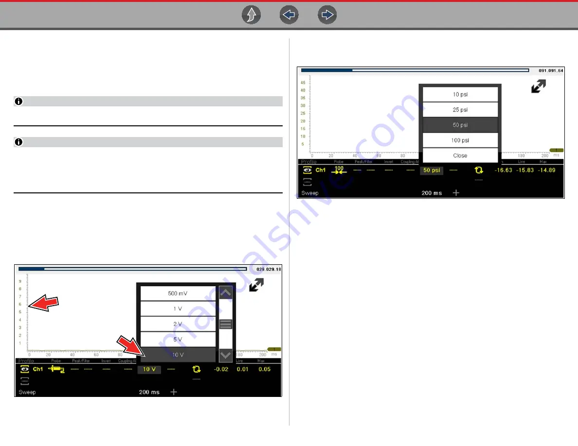
Scale (Vertical scale adjustment)

The vertical scale (Y-axis) represents what is being measured (voltage, amperage, 
pressure etc.), and the unit of measurement it is being measured in. The vertical 
scale is “always” divided into10 major divisions; how these divisions are defined, 
sets the scale of measurement. 

NOTE

Vertical scales (either channel) can be set independently. 

NOTE

Optional vertical scale preference settings are available. The Divisions option 
allow you to change (to your preference) how the vertical scale menu 
selections are represented, and the type of value that displays in the vertical 
scale icon. Se

Divisions

 on page 120. 

To adjust the vertical scale unit of measurement, select the 

Vertical Scale 

icon to 

open the vertical scale menu. Select a value then press the 

N/X

 button, to exit the 

menu. The value displayed in the vertical scale icon indicates the active value.

Example:


Selecting 10V, changes the vertical scale to a 10V volt scale. The scale 

is “always” divided by 10, therefore each division is incre

mented by 1V.

Figure 12-15 

Example:

 Selecting 50 psi displays a 50 psi scale that is divided by 10, therefore 

each division is incremented by 5 psi.

Figure 12-16 

Содержание Triton D8

Страница 1: ...ev B Previous Vehicle and Data Quick Lookups Tools Scanner OBD II EOBD Scope Multimeter Guided Component Tests Previous Vehicle and Data Quick Lookups Tools Scanner OBD II EOBD Scope Multimeter Guided Component Tests Start BC ...

Страница 2: ...ous Vehicles Data Quick Lookups Tools General Information Basic Operation Navigation Maintenance Quick Reference Information Table of Contents TOC Click a Topic Using Page Controls SureTrack On PC Guided Component Tests Scope Multimeter Wi Fi Connection The Snap on Cloud Vehicle Code Scan Customer Support Training ...

Страница 3: ...5 Scanner Overview 25 Scanner Starting Stopping 26 Features and Icons 26 Scanner Features 26 Scanner Control Icons 27 Basic Scanner Operation Quick Start 27 Vehicle Identification 28 System Selection 30 System Main Menu Options 31 Codes View Save 31 Codes Menu 31 Code Scan with Vehicle System Report 33 Viewing and Saving Data PIDs 33 Data Menu 33 Data Views List Graph 39 Locking PIDs to always dis...

Страница 4: ...Measurement Out of Range Indicator 97 Overview 97 Digital Multimeter DMM 97 Graphing Multimeter GMM 98 Lab Scope 99 Tests and Capabilities Quick Reference 100 Test Leads and Accessories 101 Channel 1 Lead 101 Channel 2 Lead 101 Alligator Clips and Probes 102 Secondary Ignition Coil Adapter Lead and Clip on Adapter optional 102 Low Amp Current Probe optional 102 Temperature Probe Adapter optional 1...

Страница 5: ...Shop Files 161 Favorites 163 Profile 163 Section 17 SureTrack On PC 169 Quick Reference 169 SureTrack Community FAQ s 169 Using SureTrack for the First Time 169 Login Scenarios 169 Finding your SureTrack Authorization Code 170 Creating a SureTrack Account 170 Use Requirements 170 Creating an Account 170 Logging In active account 173 Logging In with New Authorization Code active account 174 Logging...

Страница 6: ...Table of Contents vi Customer Support Training 190 Legal Information 193 ...

Страница 7: ...ods and test procedures It is important to perform tests in an appropriate and acceptable manner that does not endanger your safety the safety of others in the work area the equipment being used or the vehicle being tested It is assumed that the operator has a thorough understanding of vehicle systems before using this product Understanding of these system principles and operating theories is nece...

Страница 8: ...ial hazard Safety Message Example Risk of electric shock Prior to recycling the battery pack protect exposed terminals with heavy insulating tape to prevent shorting Disconnect all test leads and turn diagnostic tools off before removing the battery pack Do not attempt to disassemble the battery or remove any component projecting from or protecting the battery terminals Do not expose the diagnosti...

Страница 9: ...epresentative for availability of other functions and optional equipment Conventions The following conventions are used Terminology The terms Scanner and Scanner function are used to describe the Scanner Function s of the diagnostic tool Examples Select Scanner from the Home screen From the Scanner main menu select Continue The Scanner function provides many diagnostic tests The term select descri...

Страница 10: ...menu options Example Press the OK button Notes and Important Messages The following messages are used Notes A NOTE provides helpful information such as additional explanations tips and comments Example NOTE For additional information refer to Important IMPORTANT indicates a situation which if not avoided may result in damage to the test equipment or vehicle Example IMPORTANT Do not disconnect the ...

Страница 11: ...ist shown below then select Connect Wi Fi Applications The following integrated Repair Information Applications provide up to date service repair information directly to your diagnostic tool via wireless network connection to our Snap on Web Services Network Intelligent Diagnostics SureTrack Tire and Wheel Service within Quick Lookups Oil Specs and Resets within Quick Lookups To use these applicat...

Страница 12: ...Track Account on page 170 for instructions Reactivating SureTrack If you have recently purchased a qualifying upgrade plan you will need to reactivate your account to access SureTrack See Logging In active account on page 173 for instructions Printing Data and Screenshots Use ShopStream Connect to print data files and screenshots from the diagnostic tool See ShopStream Connect on page 179 Diagnost...

Страница 13: ...Links Basic Features page 3 Powering the Diagnostic Tool page 4 Vehicle Power page 4 Internal Battery Pack page 4 AC Power Supply page 5 Technical Specifications page 5 2 1 Basic Features 1 Touch Screen 2 Control Panel Figure 2 1 Front view 1 Built in Stand 2 Battery Cover Figure 2 2 Back view Previous Vehicle and Data Quick Lookups Tools Scanner OBD II EOBD Scope Multimeter Guided Component Tests...

Страница 14: ...eing supplied to the cable If the LED fails to illuminate check that the data cable is properly connected and then check the DLC power circuit See Data Cable Connections on page 11 for additional data cable information An optional power cable is required when testing non OBD II EOBD or models that do not have vehicle battery power B available on the DLC Contact your sales representative for availa...

Страница 15: ...ery is charging Amber indicates a battery issue This is usually caused by excessive battery temperature above 104 F 40 C which disables charging Allow the diagnostic tool to cool down before continuing operation Item Description Specification Touch Screen Resistive Touch Panel Display 8 0 inch diagonal Color LCD 800 x 480 resolution SWVGA Meter Meter Category 1 Battery Rechargeable lithium ion bat...

Страница 16: ...you attempt to turn the diagnostic tool off while communicating with the vehicle Forcing a shut down while communicating may lead to ECM problems on some vehicles Never disconnect the Data Cable when the diagnostic tool is communicating with the vehicle ECM z To turn off the diagnostic tool 1 Press the N Cancel button or select the Back or Home icon to navigate to the Home screen If applicable a s...

Страница 17: ...ram To select an item that was highlighted using the direction arrows To advance to the next screen in a series To answer Yes when a yes or no choice is given Previous Vehicle and Data Quick Lookups Tools Scanner OBD II EOBD Scope Multimeter Guided Component Tests Previous Vehicle and Data Quick Lookups Tools Scanner OBD II EOBD Scope Multimeter Guided Component Tests 1 2 3 4 5 3 Directional Thumb...

Страница 18: ... displayed See Clock Settings on page 144 for additional information The Title bar displays other information that varies depending upon what functions are being performed Other information may include The identification ID of the test vehicle Function Name Function Icon Description Scanner Used to communicate with the electronic control systems of a vehicle This function allows you to retrieve di...

Страница 19: ... a directional button to rapidly scroll through data 3 4 Screen Messages 3 4 1 Snap on Messages Periodically messages will be displayed to inform you of software updates and upgrades as well as other important information These messages require confirmation to resume tool operation Select Confirm or OK to resume operation Icon Function Icon Function Full Battery Charge Level Indicates power is bei...

Страница 20: ...mmunication Software manuals for manufacturer specific problems Message Type Description Loading and Connecting Loading and connecting messages display when the diagnostic tool is performing an internal operation such as loading a database establishing communications with the vehicle or initiating a test The message automatically clears once the internal operation is complete Confirmation Confirma...

Страница 21: ...se the supplied DA 4 data cable 1 Connect the data cable to the diagnostic tool Figure 4 1 Figure 4 1 DA 4 data cable 26 pin end connection to diagnostic tool 2 After identifying the vehicle using the Scanner or OBD II EOBD function see Vehicle Identification on page 28 review any on screen information that may be provided for data cable connection usage and DLC location Figure 4 2 NOTE On screen ...

Страница 22: ...LC locations 5 Select Continue once the data cable is connected The diagnostic tool establishes communication with the vehicle then displays a list of available tests see Scanner on page 25 for additional information 4 1 1 Optional OBD II EOBD Data Cable A shorter 6 ft 1 8 m DA 4 OBD II data cable is available as an option Contact your sales representative to purchase all optional accessories IMPO...

Страница 23: ... EOBD cable to the DA 5 adapter The DA 5 adapter connects to the manufacturer specific OBD I adapter This may be used instead of the optional OBD I data cable An optional OBD I data cable is available which allows direct connection between the diagnostic tool and the manufacturer specific OBD I adapter This may be used instead of the optional DA 5 adapter An optional U S domestic and Asian vehicle...

Страница 24: ... following Scanner demonstrations are intended to be completed in sequence 1 Vehicle Identification 2 Scan for Engine Codes and Save the Codes 3 View Configure and Save Engine Data PIDs 4 Perform a Functional Test 5 Perform a Code Scan 6 View Saved Files Codes Code Scan and Data Files 7 Activate a Previously Identified Vehicle and View Engine Data PIDs z Scanner Demo 1 Vehicle Identification The f...

Страница 25: ...o Scanner Demo 3 z Scanner Demo 3 View Configure and Save Engine Data PIDs This demonstration simulates viewing engine data PIDs in list and graph views creating a custom data list and saving the data for review at a later time Viewing PIDs 1 From the Main Menu Engine select Data Display Engine Data The Engine Data list is displayed showing all supported PIDs Use the scroll bar to view all the dat...

Страница 26: ... you that the file has been saved 4 Press Home to return to the Home screen 5 Proceed to Scanner Demo 6 z Scanner Demo 6 View Saved Files Codes Code Scan and Data Files This demonstration walks you through opening the data files saved in the previous demos 1 From the Home screen select Previous Vehicles and Data 2 Select View Saved Data A list of all saved files is displayed most current at top Co...

Страница 27: ... II EOBD Demo 2 Check Monitors Complete This Cycle This demonstration simulates a typical check of OBD monitors that have run during the current drive cycle 1 From the OBD II EOBD Service menu select Readiness Monitors 2 Select Monitors Complete This Cycle 3 With the monitor data displayed select View and then select PID list to display as a list 4 A list of monitors is displayed showing status in...

Страница 28: ...o save the note for review later 8 Select Back until you return to the OBD II EOBD Service menu 9 Proceed to OBD II EOBD Demo 6 z OBD II EOBD Demo 6 Display and Save Freeze Frame Data This demonstration walks you through a typical check of OBD Freeze Frame data and shows how to save and review the data 1 From the OBD II EOBD Service menu select 02 Display Freeze Frame Data A freeze frame list of d...

Страница 29: ...nts and may be used offline IMPORTANT Do not connect a vehicle to the diagnostic tool while using the Demonstration program The first process in accessing Intelligent Diagnostics is identifying the vehicle and then using the Scanner function to check for codes 1 From the Home screen select Scanner 2 The manufacturer vehicle make menu displays select Demonstration The simulated Vehicle ID process s...

Страница 30: ...e 5 2 5 The Top Repairs Graph Figure 5 3 shows the most common verified fixes and procedures and provides a quick indication of what other technicians have done to fix vehicles that have exhibited the same code The graph is not selectable and is continuously updated as new data is collected Figure 5 3 6 Proceed to Intelligent Diagnostics Demo 4 z Intelligent Diagnostics Demo 4 Viewing OEM Technica...

Страница 31: ...on 3 Select Continue 4 A Smart Data PID list is displayed for code P0300 Figure 5 6 Figure 5 6 Within a few seconds an audible alarm beeping is sounded indicating an armed PID was triggered and then a recording of the data is saved indicated by the onscreen message In this demo the Total Misfire PID Figure 5 7 was triggered and can be confirmed by pausing and viewing the recorded data Notice near ...

Страница 32: ...e useful in troubleshooting or validating repairs Figure 5 9 2 Select CKP Variation Learn 3 Continue through the screen prompts to see typical functional test instructions 4 Select Exit when finished 5 When finished select Back to return to the Intelligent Diagnostics Main Menu 6 Proceed to Intelligent Diagnostics Demo 7 z Intelligent Diagnostics Demo 7 Viewing the most common Real Fix for P0121 a...

Страница 33: ...in Menu 6 Proceed to Intelligent Diagnostics Demo 8 z Intelligent Diagnostics Demo 8 Viewing Tips Tips are code specific repair tips gathered from industry professionals 1 Scroll down and select the Tips card Figure 5 13 Figure 5 13 2 A list of available Tips is displayed Figure 5 14 Our selected code has only one result 3 Select the Tip to view it Figure 5 14 4 When finished select Back to return...

Страница 34: ... and OBD II code related screens e g display codes code scan The icon is also available from the Intelligent Diagnostics main menu Selecting Help Figure 5 15 starts a built in slideshow describing the basic features of Intelligent Diagnostics Figure 5 15 Slideshow example screens are shown in Figure 5 16 Figure 5 16 ...

Страница 35: ...rm necessary diagnosis and repair To learn more about how to connect this diagnostic tool to vehicles using a secured gateway visit www snapon com gateway 6 1 Basic Operation 6 1 1 Scanner Overview Scanner is a menu driven application that communicates with vehicle control modules to access diagnostic trouble codes DTCs parameter data PIDs functional tests and more To navigate the application use ...

Страница 36: ...power down the diagnostic tool A warning message displays if you attempt to shut down while the diagnostic tool is communicating with the vehicle z To exit the Scanner function 1 From any active Scanner screen select the Back icon on the toolbar The stopping communications message briefly displays followed by the Data menu 2 From the Data Menu select Back on the toolbar The stopping communications...

Страница 37: ...ur See Instant ID on page 29 for additional information Icon Function Icon Function Pause Pauses active data collection Start Capture Resumes active data collection Clear Erases all the PID data in the buffer and begins a new recording Selecting opens a confirmation message Custom Data List Opens a menu for selecting which PIDs display in the list Trigger Opens a menu that allows you to set arm an...

Страница 38: ...ication criteria z Use the following procedure to identify a vehicle NOTE The following procedure applies to most OBD II vehicles and may vary depending on the vehicle Not all vehicles support the Instant ID and or Auto ID functions 1 Connect the data cable to the diagnostic tool See Data Cable Connection OBD II EOBD Vehicles on page 11 2 Turn the vehicle ignition switch on 3 Connect the data cabl...

Страница 39: ...identified a menu of available systems and or options are displayed see System Selection on page 30 Instant ID The Instant ID function can save time when initially identifying a vehicle by automatically communicating with the vehicle to complete the vehicle identification process This function requires specific vehicle support requirements and connection procedures to operate Vehicle requirements ...

Страница 40: ...OBD II or EOBD diagnostic functions see OBD Direct on page 84 for additional information 6 2 5 System Selection After the vehicle is identified a menu of available systems and or options is displayed Figure 6 4 By default System options are displayed by category e g Engine Transmission Body Controls Instruments etc Figure 6 4 In this mode commonly used selections are at the top of the list Dependi...

Страница 41: ...ions are found on the Functional Tests Menu for some models System Tests provides specific subsystem testing Performing these tests is similar to functional tests Generic Functions lets you access certain available Generic OBD II functions from a proprietary menu 1996 and newer vehicles only Troubleshooter provides step by step procedures integrating PIDs and retrieving trouble codes when appropri...

Страница 42: ...he current ignition cycle MIL SVS or Message Requested displays ECM requests to turn on the malfunction indicator lamp MIL or service vehicle soon SVS lamp or display a driver information alert Last Test Failed displays a complete list of failed tests Test Failed Since Code Cleared displays a list of tests that failed since the last time codes were cleared from ECM memory Clear Codes The diagnosti...

Страница 43: ...and when selected it scans the vehicle control modules for codes For detailed information see Vehicle Code Scan on page 53 6 4 Viewing and Saving Data PIDs Data Topic Links Data Menu page 33 Custom Data List PID List page 35 Custom PID list cross system page 37 Changing Data Views List Graph page 40 Locking PIDs to always display at top page 41 About the Data Buffer page 41 About Cursors page 42 P...

Страница 44: ... Related System Data All System Data All System Data PID lists if supported display all available PIDs for that system In the example shown in Figure 6 11 from within an Engine system Data menu the Engine Data option can be used to display all Engine related PIDs Typically this option is named the same as the system e g Engine System Engine Data Transmission System Transmission Data etc Figure 6 1...

Страница 45: ...ID List The Custom Data List icon on the toolbar is used to select which PIDs to display Minimizing the number of PIDS displayed allows you to focus on any suspicious or symptom specific data parameters You can add or remove most PIDs from the list as certain vital PIDs may not be removed These appear in gray at the top of the list along with a lock icon and they cannot be selected NOTE Limiting t...

Страница 46: ...meters to include or remove from the custom data list 2 Create a custom data list by selecting check mark the parameters to include Figure 6 15 3 To create and view the custom list select the Accept icon Figure 6 15 Figure 6 15 4 The custom list displays Figure 6 16 Figure 6 16 Icon Description Sort Determines the order in which PIDs are listed on the screen Select Deselect hide or display individ...

Страница 47: ...ion to select PIDs from multiple lists See Custom Data List PID List on page 35 for basic operation instructions At the time of this publication only select CAN integrated 2005 and later Mercedes Benz Jaguar Chrysler Volkswagen and Audi vehicles support this feature As future diagnostic software updates occur additional vehicle makes and models may be included NOTE The total number of PIDs that ca...

Страница 48: ...and select which PIDs you want to include and then collapse the list and choose another if desired The check marks to the left of the parameter description indicate which parameters are selected for display Figure 6 19 3 Once you have selected all the PIDs you need Figure 6 20 to view the custom list select the Accept icon Figure 6 20 Figure 6 20 4 The custom list displays Figure 6 21 Figure 6 21 ...

Страница 49: ... List Graph A typical Data screen is shown in Figure 6 23 This example shows a PID list view A PID list screen is divided into two columns the left hand column has a description of the parameter and the right hand column shows the current parameter value or state PIDs are listed in the order in which they are transmitted by the ECM so variations between years makes and models will occur Data can a...

Страница 50: ...s in the left column and their current values in the right column Figure 6 25 Figure 6 25 PID List view The 1 2 and 4 Graph views divide the screen horizontally to simultaneously display data graphs for the indicated number of parameters Figure 6 26 Figure 6 26 Four graph view In graph view the text block Figure 6 27 to the left of the graph displays Top PID description Middle Current value or sta...

Страница 51: ... three parameters are locked one of them must first be unlocked before another parameter can be locked z To unlock parameters 1 Scroll through the data list and highlight the parameter to be unlocked or released 2 Select the Lock Unlock icon on the toolbar The released parameter and the lock icon disappear from the list at the top of the data list 3 Repeat Step 1 and Step 2 to release other parame...

Страница 52: ... after a slight pause to save the file Cursors are displayed in all PIDs as reference markers Cursors are retained and appear in saved data files Blue Current Position If you select Pause while collecting data a vertical blue cursor is displayed as an indicator to your position in the data and is denoted by the current position value in the counter display Cursors are displayed in all PIDs as refe...

Страница 53: ... control icons are described in Scanner Control Icons on page 27 and Common Toolbar Control Icons on page 9 After Pause is pressed Review control icons are displayed in the toolbar Figure 6 32 Use the control icons to accurately move through the data and position the blue cursor The blue vertical cursor Figure 6 32 indicates your position in the data and is denoted by the current position value in...

Страница 54: ...ure Shortcut Button on page 140 for details z To save data While capturing or reviewing data select the Save icon An onscreen message is displayed to indicate the data file is being saved Figure 6 34 Figure 6 34 Save dialog box z To view saved data on the diagnostic tool The saved file can be viewed by selecting Previous Vehicles and Data View Saved Data See View Saved Data on page 136 for basic n...

Страница 55: ... collection session will create multiple SCM files Each file will contain gray vertical cursors Figure 6 35 indicating where the data was paused Figure 6 36 z To view saved data on a PC Saved data files can also be downloaded to a personal computer PC using the Mini USB jack Once connected to the PC the data files can be printed transferred and copied using ShopStream Connect ShopStream Connect is...

Страница 56: ... is 1x Examples Top 4X Middle 1X Bottom Zoom Out Figure 6 37 Zoom examples 6 4 9 Using Triggers Trigger Description and Features Setting PID triggers allows you to configure the diagnostic tool to automatically save PID data to a file when a PID value meets an upper lower limit trigger point When a PID value meets the trigger point it activates the trigger which captures a short recording of all a...

Страница 57: ...ivated 7 Upper and Lower Limit Lines Not Armed and Activated Gray limit lines are displayed when the trigger is armed but not activated and after the trigger has been activated PID Trigger Status Icons The icons below are used to help you quickly identify the status of individual PID triggers z Setting triggers To use triggers they must be turned on set configured and then armed Use the following ...

Страница 58: ...igger point 5 Select a or press the Y a button to set the upper trigger point Figure 6 40 Trigger setup upper limit The upper trigger line changes color to gray and the lower trigger line displays in red Figure 6 41 6 Change the position of the lower trigger line in the same manner as the upper 7 When finished select a or press the Y a button to set the lower trigger level Figure 6 41 Trigger setu...

Страница 59: ...ivated Data collection is briefly paused as the Scanner captures a recording of all available PID data and saves it as a data file A gray cursor line is displayed to indicate the point at which the data was paused or saved An audible alarm is sounded A message displays indicating a data file was saved Data collection continues The activated PID trigger is disarmed Note if a different PID trigger i...

Страница 60: ...ts Reset Tests these tests reset the adaptive or learned values that are stored in the vehicle electronic control module memory Scripted Tests these tests are software routines that place the vehicle into special operating modes for performing certain repairs such as bleeding brakes with ABS Selecting Functional Tests opens a menu of test options that varies by make year and model Selecting a menu...

Страница 61: ...tion on virtually all common diagnostic trouble code DTC problems and driveability symptoms Troubleshooter information is organized into a series of diagnostic tips that are designed to quickly lead you to the root cause of a particular problem The tips are vehicle specific which means only tips that relate to the identified vehicle are presented Selecting opens a menu that may include Code Tips p...

Страница 62: ...Scanner Troubleshooter 52 Fixes provides actual repair information for related repairs Figure 6 50 Troubleshooter code tip menu Figure 6 51 Troubleshooter tip Example P0353 ...

Страница 63: ...es Figure 7 1 Vehicle System Report VEHICLE INFORMATION VIN JN8AS5MT0FW000000 MAKE Nissan YEAR 2016 MODEL Rogue ENGINE 2 5L L4 MFI QR25DE SYSTEM CodeScan LICENSE PLATE CODE SCAN RESULTS Systems Analyzed 10 Engine 0 Transmission 0 Antilock Brakes 0 Airbag 0 Body Control Module Codes 3 Electronic Power Steering 0 Intelligent Power Distribution Module 0 Meter 0 Tire Pressure Monitor Codes 3 OBDII 0 B...

Страница 64: ...l modules and opens the Code Scan results screen Figure 7 3 Figure 7 2 NOTE Selecting Clear All Codes Read by Code Scan Figure 7 2 erases all DTCs from all vehicle system modules that were read by Code Scan Selecting this function may not clear global OBD II codes on some vehicles When initially opened Figure 7 3 a progress bar is shown at the top indicating the active scanning progress Once compl...

Страница 65: ...see Vehicle System Report Snap on Cloud on page 57 NOTE The code scan can also be saved manually by selecting the Save icon 7 1 1 Total Number of Systems modules Analyzed The total number of systems analyzed is actively displayed at the top of the screen as they are scanned Figure 7 4 Code Scan systems analyzed result total Icon Function Refresh Refreshes the code scan data restarts the code scan ...

Страница 66: ...for a system in the list select the system then select the System icon Figure 7 5 Figure 7 5 System icon opens Main Menu Select the expand collapse icon Figure 7 6 on the left side of a system category title to expand or collapse a systems DTC list Figure 7 6 Expand Collapse Icon expanded result 7 1 3 Global OBDII DTCs Towards the end of the Code Scan list Global OBDII DTCs are displayed Figure 7 ...

Страница 67: ...o a Vehicle System Report that is uploaded and saved to your Snap on Cloud account if registered and connected Report examples are shown in Figure 7 1 Using The Snap on Cloud the report can be printed downloaded attached to an e mail or other social media app to share with others For additional information on using The Snap on Cloud see The Snap on Cloud on page 153 NOTE Code scan reports are auto...

Страница 68: ...de step by step instruction component specifications and troubleshooting information Real Fixes and Troubleshooter View code specific procedures tests and tips that have been gathered from actual shop repair orders and industry professionals Intelligent Diagnostics Demo An Intelligent Diagnostics walk through demonstration is provided to help you become familiar with the code specific functions of...

Страница 69: ... you do not have access to the application See Wi Fi Connection Troubleshooting on page 147 for Troubleshooting information No connection Please try again later indicates you are not currently connected to the Web Services Network except when displayed in the OBD EOBD function as Repair Information Services are not accessible in OBD EOBD mode If this message is displayed in the Scanner function it...

Страница 70: ...ired 2 Code Results Dropdown Menu Displays selectable list of all present codes 3 Top Repairs Graph Graphical display of the specific parts and procedures most frequently used to fix the selected code or symptom 4 Technical Bulletins OEM Information card Lists code specific Safety Recalls Technical Service Bulletins TSB s and OEM Campaigns 5 Smart Data card Displays a custom list of code specific ...

Страница 71: ...Repairs Graph The Top Repairs Graph Figure 8 4 shows the most common verified fixes and procedures Example In the graph shown below the most common fix for the code was replacing the intake manifold gasket This fix occurred 413 times with the most occurrences 85 at 100k miles in vehicles with up to 200k miles Figure 8 4 Top Repairs Graph multiple components Depending on the information available t...

Страница 72: ...tes the total number of Recalls TSBs and OEM Campaigns that have been found A green icon indicates a search was performed and no results were found Selecting the Technical Bulletins card Figure 8 6 provides a detailed list view of the available OEM Recalls TSBs and Campaigns Figure 8 7 Figure 8 6 Technical Bulletins card Select a topic from the list Figure 8 7 to view detailed information on the t...

Страница 73: ...t Data works best when the vehicle is idling at operating temperature with no load present Always refer to OEM service information for specific PID range limit information Selecting the Smart Data card Figure 8 9 opens the custom code specific PID list Figure 8 10 PID List View Figure 8 11 PID Graph View Figure 8 9 Figure 8 10 Figure 8 11 Selecting the Back icon opens the Smart Data main menu Figu...

Страница 74: ...erride the preconfigured Smart Data values Note Manually set triggers will display upper and lower trigger limit lines in the graph When a trigger is activated Data collection is briefly paused as the Scanner captures a recording of all available PID data and saves it as a data file An audible alarm is sounded A message displays indicating a data file was saved Data collection continues The activa...

Страница 75: ...p on off and reset certain control module values e g reset fuel trim directly from the diagnostic tool to confirm the operation of components and validate repairs Intelligent Diagnostics Functional Tests and Reset Procedures operation and navigation is similar to the Functional Tests within the Scanner function For additional information see Functional Tests on page 50 Figure 8 14 Additional Funct...

Страница 76: ...en Figure 8 17 depending on the vehicle These options are not DTC related but are vehicle specific related and may be useful in troubleshooting or validating repairs Figure 8 17 After a test is selected a component test sub menu opens The component test sub menu may include various test options and a Component Information selection Figure 8 18 if supported Figure 8 18 Guided Component Tests provid...

Страница 77: ...eal Fix displayed on the Main Menu above the Real Fixes card is the most common Real Fix to date NOTE Fixes have been researched and obtained from professional automotive OEM and specialty technicians from a vast range of repair shops Fixes may not be available for every vehicle and or DTC Figure 8 21 Figure 8 22 Select a Related Real Fix from the list Figure 8 22 to view detailed information abou...

Страница 78: ...industry professionals NOTE Tips have been researched and obtained from professional automotive OEM and specialty technicians from a vast range of repair shops Tips may not be available for every vehicle and or DTC Figure 8 24 Select a Related Tip from the list Figure 8 25 to view the information Figure 8 26 Figure 8 25 Figure 8 26 P0121 P0121 Throttle position sensor ...

Страница 79: ...es and information Scanner Functional Resets NOTES Oil Specs and Resets vehicle coverage is the same as the Scanner vehicle coverage Not all vehicles may have on board diagnostic tool reset capabilities or have information available To use the Oil Specs and Resets feature you must have authorized access contact your sales representative for details The diagnostic tool is equipped with the ability ...

Страница 80: ...re 9 1 Home Screen Quick Lookups Icon Figure 9 2 Scanner System Menu Oil Specs and Resets Option 1 Follow the screen prompts to select the vehicle Manufacturer Year and Model 2 Select OK to confirm the vehicle 3 If applicable Follow the screen prompts to select the vehicle sub model options 4 After the Fluid Capacity screen displays navigate to either of the following options Perform a service int...

Страница 81: ...tion may include Vehicle application information Oil capacity specifications with or without oil filter Oil rating weight and type Special notes Figure 9 3 Typical Oil Specification Result Icon Icon Name Description Fluid Capacity Displays OEM recommended engine oil specification and capacity information Functional Reset Scanner Opens the Scanner service reset menu for the selected vehicle providi...

Страница 82: ...n vehicle support A grayed out or non selectable icon indicates that functional resets are not available for the selected vehicle Service interval reset menus and selections will vary by manufacturer 1 Select the Functional Reset icon The Scanner function opens to the service interval reset menu for the selected vehicle 2 Select the applicable menu option s to perform the functional reset 3 Read a...

Страница 83: ... controls accelerator pedal information or media center controls multi function switch etc Special notes and or instructions Theory of operation NOTE During content download icons may be used as image place holders until the image is fully downloaded and can be displayed Use the scroll bar or directional buttons b d to scroll up down to view all of the information The following are examples Figure...

Страница 84: ... need to see an image in greater detail tap the image to select it Figure 9 6 Figure 9 6 Selecting an image opens it in a viewer window Figure 9 7 Figure 9 7 Use the zoom and pan features described in this section to adjust the image as needed Zoom From the image viewer window select the and icons from the toolbar to incrementally increase or decrease the image displayed Figure 9 8 Figure 9 8 ...

Страница 85: ...Quick Lookups Oil Specs and Resets 75 Pan To move the image touch hold and drag the image on the screen to reposition it Figure 9 9 Figure 9 9 ...

Страница 86: ...ool is equipped with the ability to connect to a Wi Fi network however the connection is solely dedicated to our Snap on Web Services Network Before you begin using an integrated Information Service you must connect to a wireless network See Configure Wi Fi on page 145 for instructions If you experience a wireless network connection loss Tire and Wheel Service information will not refresh and or m...

Страница 87: ...nclude Instructions for manually resetting the TPMS indicator using on board vehicle functionality Special notes and or instructions Theory of operation During content download progress messages may display until the image is fully downloaded and can be displayed NOTE When viewing images within the displayed OEM procedures use the same navigation functionality e g pan zoom etc as previously descri...

Страница 88: ...nd can be displayed NOTE When viewing images within the displayed OEM procedures use the same navigation functionality e g pan zoom etc as previously described in Oil Specs and Resets see Viewing Images on page 74 Use the scroll bar or directional buttons b d to scroll up down to view all of the information The following are examples Figure 9 13 of typical TPMS service procedures Instructions and ...

Страница 89: ...uctions as written NOTES Scanner functions require connection and communication with the vehicle Functional tests resets are not available for all vehicles and will vary depending on vehicle support A grayed out or non selectable icon indicates that functional resets rests are not available for the selected vehicle Service test reset menu titles will vary by manufacturer The following screen examp...

Страница 90: ...tions Fitment Selecting Tire Wheel Specifications displays OEM tire and wheel specifications Figure 9 15 Typical information may include Tire size and pressure Wheel hub stud size and lug torque Wheel size Figure 9 15 Typical Tire and Wheel Specification Result ...

Страница 91: ... 84 Connector Information page 87 Manual Protocol Selection page 87 Codes page 82 Pending Codes page 82 Readiness Monitors page 85 MIL Status page 85 Fast Track Troubleshooter page 85 01 Display Current Data page 85 02 Display Freeze Frame Data page 85 03 Display Trouble Codes page 85 04 Clear Emissions Related Data page 85 05 06 07 Display Test param Results page 86 06 On board Monitored Systems ...

Страница 92: ...play the SureTrack results message below the toolbar However SureTrack is not accessible in OBD II EOBD mode SureTrack is only accessible in the Scanner function where the vehicle has been identified Figure 10 2 DTC Results Screen Codes The Codes option displays a list of current emission related DTCs OBD II EOBD Codes have a priority according to their emission severity The priority of the code d...

Страница 93: ...ehicle Communication Software Manual for additional information Readiness Monitors This test checks the status of the readiness monitoring system An OBD II EOBD control system runs continuous and periodic tests to check the status of emission related subsystems to gauge the integrity of the electronic operations Two options are available for Readiness Monitors Monitors Complete Since DTC Cleared d...

Страница 94: ...displayed The diagnostic tool establishes a communication link with the test vehicle then opens an information screen Figure 10 4 Figure 10 4 Protocol information The information screen shows how many control modules were detected which ECM is communicating and which communication protocol is being used 3 Select Continue A Select Service menu of available tests opens Readiness Monitors on page 85 ...

Страница 95: ...toms for most vehicles covered by the vehicle communication software 01 Display Current Data Use this test to display the serial data transmitted by the selected vehicle electronic control module ECM The main body of the screen has two columns the left hand column is a description of the parameter and the right hand column is the parameter value or state Viewing options and operations are the same...

Страница 96: ...st 06 On board Monitored Systems This option opens a menu of tests from the monitored systems The available data is for specific systems and components that the on board diagnostic system monitors continuously such as misfire or non continuously such as the catalyst system Making a menu selection displays the test results 07 DTCs Detected During Last Drive This test opens a record of any DTCs that...

Страница 97: ...hich one and how to connect it displays 4 Select Continue Information on where to locate the vehicle diagnostic connector displays 5 Select Continue to return to the System menu Manual Protocol Selection Communication protocol is a standardized way of transferring data between an ECM and a diagnostic tool Global OBD may use the following communication protocols ISO 15765 4 CAN ISO 27145 WWHOBD CAN...

Страница 98: ... specific tests and resources that allow you to quickly perform common tests review basic reference information and more Main Topic Links Training and Classes page 88 Screen Layout and Icons page 91 Operation page 92 Component Information page 93 Tests page 94 Saving and Reviewing Data Files page 95 11 1 Training and Classes Training and Classes is a companion feature to the Guided Component Tests...

Страница 99: ...nt A T Line Pressure and Shift Solenoid A T Line Pressure Test EGR Temperature Sensor and EGR Vacuum Exhaust Back Pressure Test Fuel Pressure and Fuel Pump Current and Voltage Fuel Pressure Test 11 1 2 Features and Benefits Selecting Features and Benefits provides basic feature description and operational information about the diagnostic tool Additional information is provided for ShopStream Conne...

Страница 100: ...ed Loop Oxygen Sensor Types Understanding Oxygen Sensors includes configured meter test Snap on Automotive Theory provides basic theory information on multiple topics including Air Conditioning Diagnosing Battery Draws Diesel Particulate Filters Electronic Parking Assistance HID Headlights Hybrid Vehicles LIN BUS Supplemental Restraint Systems Tire Pressure Monitoring TPMS Test Tips provides basic...

Страница 101: ... can adjust the zero baseline position 0 value of the signal on the horizontal scale by touching and dragging the zero baseline marker 11 2 2 Guided Component Tests Control Icons Guided Component Tests toolbar control icons may vary depending on the active function or test A yellow frame surrounding an icon highlighted indicates it is selected Other control icons not shown are described in Common ...

Страница 102: ...le is identified a list of Systems is displayed z To select a system and component to test 1 Select a system from the list Figure 11 3 Figure 11 3 Systems Menu A list of Components and or sub systems is displayed Figure 11 4 2 Select a Component to continue Figure 11 4 Component Menu Depending on the vehicle and component selected different options and sub menus may be displayed Information and te...

Страница 103: ...t Information is displayed Figure 11 6 Figure 11 6 Component Information Screen Screens are divided into sections to quickly guide you to the correct information available sections and information will vary Operation provides a general description of component operation Tech note provides component related tips e g common failures or faults additional information may include OEM service updates an...

Страница 104: ... by the type of component as well as the make model and year of the vehicle Figure 11 7 Component Test Menu NOTE An additional selection may be required for some Component Tests e g selecting front or rear for an oxygen sensor The test screen displays Figure 11 8 A Guided Component Test screen initially opens with the information panel below the main body Use the scrollbar to display hidden inform...

Страница 105: ...s preconfigured for most of the component tests However if the need to change channel settings is needed adjustments can be made by selecting the Control Panel icon from the toolbar to display the Control Panel Figure 11 11 For additional information on channel settings see Control Panel and Settings on page 106 Figure 11 11 Control Panel Channel Controls 11 3 3 Saving and Reviewing Data Files Sav...

Страница 106: ...128 12 1 Safety Information IMPORTANT Over Voltage Installation Category CAT This Scope Multimeter is rated as a Category CAT 1 device The maximum rated transient over voltage impulse is 500 volts DO NOT exceed the rated transient over voltage Risk of electrical shock Read the Safety Information provided for important warnings on the use of this product This product is intended for Measurement Cat...

Страница 107: ...ated as a Category CAT 1 device The maximum rated transient over voltage impulse is 500 volts DO NOT exceed the rated transient over voltage 12 2 1 Digital Multimeter DMM The digital multimeter gives you the ability to quickly make precise common electrical measurements e g DC and AC voltage resistance and amperage on circuits and components to verify operation The meter displays measurements in a...

Страница 108: ...ed to the lab scope sweep scales that use relatively short time intervals e g milli and micro seconds This allows you to monitor a signal over a longer period of time when looking for erratic glitches or dropouts To use the GMM select the Scope Multimeter icon from the home screen then select Graphing Multimeter from the menu See Tests and Capabilities Quick Reference on page 100 for a list of ava...

Страница 109: ...hen performing diagnostics To use the lab scope select the Scope Multimeter icon from the home screen then select Lab Scope from the menu See Tests and Capabilities Quick Reference on page 100 for a list of available testing functions Specifications Function Range Accuracy Comments Signal Measurement Ch 1 yellow jack Ch 2 green jack Each channel input is referenced to common ground GND black jack ...

Страница 110: ...d DC current is passed through the diode to measure the voltage drop between the two connected test leads Typical setup for positive to negative current flow positive lead anode side and negative cathode side a Frequency Measures the number of times a signal repeats itself per second Used to measure frequency of signals such as CKP CMP and wheel speed sensors a Pulse Width Measures the on time of ...

Страница 111: ...ally connected to the standard ground lead therefore it does not need to be connected to the diagnostic tool ground jack 12 4 2 Channel 2 Lead The shielded green lead is used with channel 2 and is color matched with the channel 2 jack on the diagnostic tool This lead also includes a black right angle stackable ground plug Figure 12 3 Green Channel 2 lead a a 100 PSI Pressure Used to measure pressu...

Страница 112: ...gure 12 5 Secondary Ignition Coil Adapter Lead and Clip on Wire Adapter NOTE Contact your sales representative for additional information on OEM specific CIC and COP secondary ignition adapters 12 4 5 Low Amp Current Probe optional The Low Amp Current Probe is used measure AC or DC current up to 60A This probe includes two scales 0 to 20A and 0 to 60A that can be used to provide accurate and relia...

Страница 113: ...on Sensor CKP Camshaft Position Sensor CMP Accelerator Pedal Sensor APP Wheel Speed Sensor WSS Signals and more representative of a 2012 BMW 328i Sedan Figure 12 9 12 5 General Information This section describes the general Scope Multimeter control icon functions screen layout and optional settings The screen layout and control icon functions are shared between the digital graphing multimeters and...

Страница 114: ...e frame and opens the control panel at the bottom of the screen while switching active selection focus to the Show Hide or Probe icon in the Control Panel b In split screen mode control panel open when selected this icon becomes surrounded by a white frame and switches active selection focus to the Show Hide or Probe icon in the Control Panel Note Switching active selection focus to the Control Pa...

Страница 115: ... end 1 Ground Jack Black 2 Channel 1 Jack Yellow 3 Channel 2 Jack Green Figure 12 11 Scope Multimeter Test Lead Jacks 12 6 2 Test Lead Probe Calibration Certain tests may display a confirmation prompt asking Do you wish to calibrate this probe before continuing with the test As general practice it is important to ensure the test probe is calibrated before testing to ensure accurate results Typical...

Страница 116: ... control panel can be toggled on off by selecting the Expand Collapse Icon to switch the screen between full and split test meter views 1 Cursors 2 Control Panel Icon 3 Data Buffer Position Indicators graphical and numerical position indicators 4 Zero Base Line Indicators 5 Control Panel contains channel trace controls and settings Figure 12 13 Scale Sweep and Probe Settings The most common and ty...

Страница 117: ...nge to your preference how the vertical scale menu selections are represented and the type of value that displays in the vertical scale icon See Divisions on page 120 To adjust the vertical scale unit of measurement select the Vertical Scale icon to open the vertical scale menu Select a value then press the N X button to exit the menu The value displayed in the vertical scale icon indicates the ac...

Страница 118: ...eep Scale icon indicates the active sweep setting NOTE The sweep setting applies to all channels and cannot be set independently per channel To adjust the sweep scale unit of measurement value select the Sweep Scale icon to open the sweep scale menu Select a value then press the N X button to exit the menu 1 Sweep Scale 2 Sweep Scale Menu 3 Sweep Scale Icon Figure 12 17 Example Selecting 500ms cha...

Страница 119: ...nformation see Test Lead Probe Calibration on page 105 Probe test Options Menu Option Probe Device Used Test Lead Volts DC Standard Channel 1 and 2 test leads with alligator clips or test probes Vacuum 100 optional 0 100 psi pressure transducer with pressure adapter Pressure 100 Pressure 500 optional 0 500 psi pressure transducer with pressure adapter Pressure 5000 optional 0 5000 psi pressure tra...

Страница 120: ...4 Peak Detect maximizes sampling rate 5 Filter removes signal noise or interference 6 Invert switches signal polarity 7 Coupling AC blocks the DC portion of signal 8 Scale Vertical scale adjustment adjusts vertical scale 9 Trigger turns triggering on off and sets direction of trigger slope 10 Refresh clears Min Max and Live values and resets to zero 11 Min Live and Max Display Panel displays lowes...

Страница 121: ...er memory to plot a waveform across the screen No preference is given to any point during the selection process NOTES Turning peak detect off is suitable for basic measurements and viewing waveforms e g oxygen O2 or Cam sensor when capturing fast events is not necessary The longer the time sweep the greater the chance a glitch could be missed because it occurred in between the sample points saved ...

Страница 122: ...rforming a throttle position TP sensor sweep test 5 volt scale In addition the filter is also helpful for low amp probe tests as a low voltage scale is used to measure the output of the probe due to the conversion factors of the probe Example For a probe with a conversion factor of 100 mV A connected to a 2 amp load the scope uses a 200 mV scale to measure the output of the probe The scope convert...

Страница 123: ...ons crosses the trigger point the trace will start Trigger conditions Vertical scale position amplitude Sweep position the horizontal scale position or position in time Slope direction the direction the trace must be moving up rising or positive or down falling or negative when crossing the trigger point NOTES Triggers can be set on any channel however only one trigger can be activated used at a t...

Страница 124: ...ect and drag it into position using the touch screen 4 To more accurately position the trigger marker select the Trigger Position Control icon Figure 12 22 The trigger position control panel opens 5 Use the directional controls provided or the thumbpad directional controls to move the trigger marker into position Figure 12 21 Sweep and vertical scale values are provided in the trigger position con...

Страница 125: ...toolbar 3 Select Settings Configure Scope Meter Trigger Mode from the menu selections 4 Select either Auto Trigger or Manual Trigger 5 Select Back or press the N X button to navigate back to the test meter screen Threshold NOTE The Threshold function is only available in the Graphing Meter function for specific tests This function may also be referred to as Auto Threshold Select ATS The Threshold ...

Страница 126: ...Cursors feature is only available in the lab scope and Graphing Meter functions Two vertical cursors are provided that allow you to make precise signal measurements when determining signal characteristics such as amplitude at specific points and cycle time duration or frequency Using cursors can also be helpful when performing certain diagnostic tests such as O2 sensor rich lean switch time fuel i...

Страница 127: ...r measurements Signal amplitude at two points Signal amplitude difference delta between two points Cursor position in time at two points Difference delta in time between the cursors Frequency frequency of the signal for the time period between cursor 1 and 2 The cursor measurements panel contains values for each channel in two displays The amplitude and delta display is provided in the channel spe...

Страница 128: ...ope connectors and black RCA type adapter connector See Secondary Ignition Coil Adapter Lead and Clip on Adapter optional on page 102 Secondary Ignition Adapters available Different secondary ignition coil adapters are available as optional equipment These adapters attach to either the secondary lead spark plug lead or directly to the secondary ignition coil in order to pick up the secondary ignit...

Страница 129: ...robe setting 8 If needed turn the Invert function on Once a signal is displayed further channel settings may be required to display the pattern characteristics you a looking for Figure 12 26 Typical Secondary Ignition Signal 12 7 Optional Settings The following optional Scope Meter settings are available and can be set to your preference Trigger Auto Manual Mode Optional Setting on page 115 Displa...

Страница 130: ... from the Home screen 2 Select Settings from the Tools and Setup menu 3 Select Configure Scope Meter from the Settings menu 4 Select Divisions from the menu 5 Select either option Trace Settings see Trace Settings on page 120 Display Settings see Display Settings on page 122 6 Select the Back icon or press the N X button to return to the Settings menu Trace Settings The Trace Settings option allow...

Страница 131: ...e is always divided by 10 therefore each division is incremented by 1V Figure 12 29 Trace Per Division changes the dropdown vertical scale menu selections to div mode which in turn changes the vertical scale to represent by division represents variable what is being measured voltage amperage pressure etc Example Figure 12 30 Selecting 1 0V div displays a vertical scale divided by 10 The vertical s...

Страница 132: ...hanges the value displayed in the Vertical Scale icon Display Full Scale displays the value of the entire full scale Example Figure 12 31 If the vertical scale is set to 1V the value displayed is 1V Figure 12 31 Display Per Division displays the graduation value of the major scale divisions Example Figure 12 32 If the vertical scale is set to 1V the value displayed is 0 1V Figure 12 32 ...

Страница 133: ...low room for the new data being stored The most recent data is always available for review when the scope is paused and can be reviewed using the toolbar controls As a visual aid a graphic Data Buffer Slider Figure 12 33 1 is located at the top of screen and indicates the position of the current displayed frame of data in relation to the entire buffer memory capacity Note In Review Mode the slider...

Страница 134: ...n also help in avoiding aliasing if the sweep time is too great for the waveform being captured Using peak detect is not appropriate for every instance but when using longer sweep settings it can help increase the capture time by allowing you to capture more than you could without it and still capture dropouts and points of interest See Peak Detect on page 111 for more information For additional i...

Страница 135: ... magnification level e g 2X setting moves 2 frames 16X setting moves 16 frames When the Zoom icon is selected the display defaults to the Max magnification level and a dropdown scroll menu will display Figure 12 36 The dropdown menu allows you to select the display magnification level from a range of 1X to 512X Max The Max maximum option displays all data captured on one screen NOTE It is importan...

Страница 136: ... Magnification Level Max shown 4 Zoom Cursor Figure 12 36 NOTE To quickly identify a glitch in a pattern it may be easier to initially view the waveform at a higher magnification level e g 256X or Max to display the entire captured waveform find the area of interest and then lower the zoom level to 8X or 2X to review that area in detail See the following figures and the Zoom Example on page 127 Fi...

Страница 137: ... more detail Figure 12 41 in the area where the cursor was placed by the glitch Figure 12 41 12 9 Saving Data Files Selecting the Save icon writes the data stored in buffer memory to a file Saving data files is useful when trying to isolate an intermittent problem or to verify a repair during a road test The saved file can be played back similar to a movie clip by selecting Previous Vehicles and D...

Страница 138: ... or make a measurement NOTE Testing information and known good waveform libraries may also be available from other sources e g SureTrack ShopKey Pro or other online sources Obtaining correct testing reference information can be a key advantage in making sound repair decisions Listed below are a few basic questions to help narrow down the testing direction to follow Are you looking to make or test ...

Страница 139: ... See Channel Settings on page 110 At this point you should have a signal displayed that will allow you to see the overall signal characteristics and allow you to begin your diagnosis Comparing your captured waveforms to known good waveforms can be a time saver and provide supporting evidence when trying to determine a fault See Using Known Good Waveforms on page 129 for additional information 12 1...

Страница 140: ...stic tool Ensure the signal and ground connections are clean and secure at the test points and diagnostic tool Ensure the polarity of the test leads connections are correct If using stackable connectors try to isolate or only connect the leads being used to capture the signal Make sure the ground lead is providing a direct ground from the circuit to the diagnostic tool test lead jack Isolate the t...

Страница 141: ...cro 0 000001 or 10 6 or 1 1 000 000 m milli 0 001 or 10 3 or 1 1 000 c centi 0 01 or 10 2 or 1 100 k kilo 103 or 1 000 M mega 106 or 1 000 000 Electrical Units Symbol Description Equivalents V Voltage V I R I Current I V R R or Ω Resistance R V I Hz Frequency ƒ freq 1 T time or 1 cycle per second Voltage µV microvolt 1 µV 0 000001 V mV millivolt 1 mV 0 001 V V volt 1 V 1000 mV kV kilovolt 1kV 1 00...

Страница 142: ... incorrect signal to be displayed and or causes a trigger to malfunction due to the input signal exceeding the sample rate of the scope Amperage The strength of an electric current expressed in amperes Amplitude Vertical magnitude level or position of a signal or the varying quantity from its zero value Buffer An electronic reservoir for temporary storage of data Cursor Onscreen markers used to me...

Страница 143: ...bbreviation Description Pulse Width Modulation PWM A signal that continuously cycles on and off while the on time varies within each cycle RMS The RMS root mean square value of alternating currents and voltages is the effective current or voltage applied rather than the peak current or voltage measurable The AC RMS voltage value can be defined as the equivalent DC voltage of the AC voltage measure...

Страница 144: ...ed voltage produced by the collapsing magnetic field in a coil when the current through it is abruptly terminated Waveform The graphic representation form of a signal over time which the trace displays on the screen Zero Base Line Reference setting or 0 level of a graph scale Term Abbreviation Description ...

Страница 145: ... identification of the last twenty five vehicles tested so there is no need to go through the complete vehicle identification sequence when performing a retest after repairs have been made The oldest vehicle record is deleted when a new vehicle is identified once there are twenty five vehicles on file Figure 13 1 Vehicle history list z To select from the vehicle History 1 Select Previous Vehicles ...

Страница 146: ...of 50 files are displayed To view all if more than 50 files stored transfer the files to a PC and use ShopStream Connect See Connect to PC File Transfer on page 140 for additional information z To review a saved data file or image 1 Select Previous Vehicles and Data from the Home screen 2 Select View Saved Data from the menu 3 Select a file to review from the list 13 1 3 Viewing Codes and Code Sca...

Страница 147: ... 13 5 arrow to open Intelligent Diagnostics If Intelligent Diagnostics is active and data is available additional troubleshooting information will also be displayed Figure 13 5 Viewing Printing the Code Scan Report Once saved the code scan report can be viewed and printed using ShopStream Connect see Printing the Code Scan Vehicle System Report on page 182 ...

Страница 148: ...s displays Select the file s to be deleted using the checkboxes Use the Select All Deselect All icon as necessary 1 Select All Deselect All Icon 2 Delete Icon 3 Selected files to be deleted Figure 13 6 2 The files with checkboxes will be deleted To delete the files select the Delete icon 3 A confirmation message displays Select an option OK permanently deletes the selected file Cancel returns to t...

Страница 149: ... Theme page 142 Font Type page 143 Backlight Time page 143 Touch Screen Calibration page 143 Time Zone page 144 Clock Settings page 144 Daylight Savings Time page 144 Time Format page 145 Date Format page 145 AUTO VIN page 145 14 1 Tools Menu The following options are available from the Tools menu Connect to PC File Transfer use to transfer and share files with a personal computer PC Get Connected...

Страница 150: ...ation and operation instructions 14 1 3 Configure Shortcut Button This feature allows you to change the function of the Shortcut button Options are Brightness opens the brightness setting screen Save Screen saves a bitmap image of the visible screen Save Movie writes PID data from buffer memory to a file for future playback Show Shortcut Menu opens the menu so you can quickly select from any of th...

Страница 151: ... lighting conditions Font Type on page 143 switches between standard and bold text for better visibility Backlight Time on page 143 adjusts how long the screen stays on with an idle diagnostic tool Touch Screen Calibration on page 143 calibrates the touch screen display Date Time options include Time Zone on page 144 sets the internal clock to the local time standard Clock Settings on page 144 set...

Страница 152: ... and a please wait message momentarily displays followed by the Home screen The new toolbar setting is now active High Contrast Toolbar This option allows you to switch to a high contrast toolbar This toolbar features black and white icons with crisp graphics that are easier to see in poor lighting conditions or bright sunlight Figure 14 5 High contrast toolbar Selecting opens a menu with two choi...

Страница 153: ...plete the touch screen calibration sequence once it has begun Never turn off the diagnostic tool while a screen calibration is in process z To calibrate the touch screen 1 Select Tools from the Home screen 2 Select Settings System Settings Display Touch Calibration The calibration screen opens Figure 14 6 Figure 14 6 Touch screen calibration 3 Select the center of each alignment indicator on the s...

Страница 154: ... Select the up icon on the screen or press the up b button to incrementally increase the number in the highlighted field Select the down icon on the screen or press the down d button to incrementally decrease the number 5 Select the check a icon on the screen or press the Y a button to move the highlight to the next field 6 Repeat Step 4 and Step 5 until the correct time is displayed 7 Select the ...

Страница 155: ...feature Configure Wi Fi Selecting Configure Wi Fi allows you to configure and troubleshoot the diagnostic tool Wi Fi connection see Wi Fi Connection Troubleshooting on page 147 Configuring Scanner This option allows you to change the scanner display to toggle scales on and off Scales are the graduations and values that display on the horizontal axis at the base of the parameter graphs The waveform...

Страница 156: ...ings see Optional Settings on page 119 Configure Units Selecting opens a dialog box that allows you to choose between US customary or metric units of measure for various units Figure 14 10 Configure units menu z To change the units setup 1 Select Tools from the Home screen to open the menu 2 Select Configure Units to open the menu 3 Select an item from the Configure Units menu 4 Select a setting f...

Страница 157: ...f Wi Fi is Connected page 147 Turning Wi Fi On and Connecting to a Network page 148 Add Network Advanced Connecting to a hidden network page 149 Wi Fi Testing page 149 Wi Fi Troubleshooting and Status Messages page 150 15 1 Checking if Wi Fi is On Off The Wi Fi indicator is displayed in the title bar when Wi Fi is on 15 2 Checking if Wi Fi is Connected Check the Wi Fi indicator in the title bar 1 ...

Страница 158: ...required when choosing a secured protected network Enter the password using the on screen keyboard and then select the check mark on the keyboard to continue Networks with a proxy challenge page or that require the user to accept terms of usage are not supported Wi Fi performance varies depending on your wireless network equipment and ISP 5 Select Connect to connect to your desired network or Canc...

Страница 159: ... your IT administrator to determine the type 4 Enter the network name or SSID 5 Enter the network password 6 Select Connect at the prompt to connect to the network 7 Select OK at the confirmation screen to continue using this connection or Forget to disconnect this connection 15 5 Wi Fi Testing If you are experiencing network connection issues an automated testing feature is available to quickly t...

Страница 160: ...erence as used in the following troubleshooting chart Router The data transmission device directly connected to your ISP Remote Wireless Access Point A wireless connection device between the router and your diagnostic tool Wi Fi Radio The internal diagnostic tool radio transmitting and receiving Wi Fi signals Network Connection Also called Wi Fi connection The configured Wi Fi router connection th...

Страница 161: ... networks have been deleted forgotten turn off the diagnostic tool 5 Turn on the diagnostic tool and connect to the desired Wi Fi network see Turning Wi Fi On and Connecting to a Network on page 148 General Troubleshooting Problem Possible Cause Corrective Action Repair Information Applications e g Intelligent Diagnostics Oil Specs and Resets are not available Access has expired Contact your sales...

Страница 162: ...Cause Displayed Tip Message Corrective Action Checks Hardware Wi Fi radio not responding and or will not turn off Contact Customer Support for assistance Wi Fi radio not responding and or will not initialize Missing or corrupt firmware file s Router This device is not connected to a router Check Wi Fi signal strength out of range or interference Move closer within 50 Ft 15 M or into a direct open ...

Страница 163: ...twork page 164 Logging Out of The Snap on Cloud page 168 16 1 Key Features Automatically transfer code scan reports to The Snap on Cloud Access and manage your Snap on Cloud account using your mobile device or PC Share send files via e mail or other mobile apps Tag files attach a descriptive key name to help you organize and search files Use the Search function to quickly find files by Tag Descrip...

Страница 164: ...a mobile device or PC visit https ALTUSDRIVE com and select Create Individual Account from the Login screen 4 Enter the required information and create a Username and Password then select Create 5 At the Success confirmation screen select Done 6 Log in using your Username and Password 7 Answer the security questions then select Submit 8 From Technician Profile Manager select the Device Management ...

Страница 165: ...s is normal any displayed set of PIN and Code numbers may be used to register 3 Using a mobile device or PC visit https ALTUSDRIVE com and select Login upper right screen 4 Log in using your ShopKey Pro or SureTrack Username and Password 5 Open the Profile Manager additional login may be required 6 From the Device Management tab select Add Device 7 Enter your Serial Number PIN Code and Device Name...

Страница 166: ... 16 1 This is normal any displayed set of PIN and Code numbers may be used to register Figure 16 3 16 4 Using the Snap on Cloud To use The Snap on Cloud A Snap on Cloud account is required see Registration Getting Started on page 153 The diagnostic tool must be connected to a Wi Fi network see Wi Fi Connection Troubleshooting on page 147 16 4 1 Logging in to Snap on Cloud registered user z Logging...

Страница 167: ...inks My Files see page 157 Search see page 161 Favorites see page 163 Profile see page 163 Figure 16 7 16 4 3 My Files My Files displays all the files uploaded from the diagnostic tool Figure 16 9 Each file is displayed in a navigation card Figure 16 8 2016 Audi A8 2015 Fiat 500 F 2015 BMW 7 Series F04 2001 Ford F150 F09 2014 Chrysler Town Country 2015 BMW 4 Series GC 2015 Fiat 500 F 5 3L 2 25 201...

Страница 168: ...lect to delete the file from The Snap on Cloud 5 Favorites Icon See Favorites on page 163 for additional information 6 Shop Files See Shop Files on page 161 for additional information 7 Link icon See Sharing E mail an Individual File Link icon on page 159 for additional information Selecting a file opens the File Details The File Detail screen allows you to edit file metadata See File Detail Tags ...

Страница 169: ...ace return is added as a tag and is displayed in the Active Tag field 7 Active Tag s Displays the active tag s Tags can include the good or bad entry from the Known Good Bad checkboxes and text entered in the file Name Description and Tag fields Each entry is automatically preceded with the symbol Sharing E mail an Individual File Link icon To share a file 1 Select the Link icon Figure 16 12 on th...

Страница 170: ... from the upper toolbar Figure 16 14 2 Select Share My Gallery 3 Select Copy to Clipboard Figure 16 15 from the pop up window Figure 16 15 4 Open your e mail text social media etc app and paste the URL into a message to share with others The URL link that is sent is only displays The Files File Names Your User Name Date the Files were posted Files Descriptions Contact 1 Contact 2 ...

Страница 171: ...e s with others via e mail text social media etc from a permanent location in the cloud Unlike sharing a file s from My Files the link is permanent and will work even if the original file is deleted Shop Files links are useful when sharing a file with a customer that is not a registered Snap on Cloud user that just needs to see the file and or may need access to the file in the future Note The fil...

Страница 172: ...xt message with the link attached ready to be sent Send via Email your system default e mail application will open a new message with the link attached ready to be sent Copy to Clipboard open your e mail text social media etc application and paste the URL into a message to share with others To share all files in Shop Files 1 From Shop Files select the Menu icon Figure 16 20 from the upper toolbar ...

Страница 173: ...0 F09 2014 Chrysler Town Country 2015 BMW 4 Series GC 2015 Fiat 500 F 5 3L 2 25 2019 11 22 34 AM 2014 Chrysler Town Country 2 25 2019 11 22 34 AM 2017 Fiat 500 F 5 3L 2 25 2019 11 22 34 AM 2015 BMW 7 Series F04 3 6L 2 25 2019 11 22 34 AM 2017 Fiat 500 A 5 0L 2 25 2019 11 22 34 AM 2001 Ford F150 F09 4 6L 2 25 2019 11 22 34 AM 2016 Audi A8 2015 Fiat 500 F 2015 BMW 7 Series F04 2001 Ford F150 F09 201...

Страница 174: ...ing Out of The Snap on Cloud on page 168 Open online Help to assist in Registering Your Device Figure 16 24 My Network Selecting My Network Figure 16 24 allows you to add others to your file sharing network Enter the contacts name phone number and or email at the prompt Add as many contacts as you need The Contact Names you enter will appear in the Share Link pop up screen Figure 16 26 when you se...

Страница 175: ... SureTrack user please note that Profile Manager is the same as your SureTrack Profile Manager Any changes you make will also be reflected in your SureTrack account Profile Manager includes five tabbed categories to help you manage your account information Account on page 165 Personal Information on page 166 Expertise on page 166 Profile Picture on page 166 Device Management on page 167 Account Th...

Страница 176: ...rtise SureTrack users only Select the vehicles from the list that you have expertise with When a question is asked within the SureTrack community about one of the selected vehicles you will receive an email with the details and a link back to the question Figure 16 29 Profile Picture This screen allows you to personalize your profile picture by selecting one of the provided images Your Name Your N...

Страница 177: ...r Diagnostic Tool Enter the device Serial Number serial number of the device PIN specific PIN associated to the device Code authorization code specific to the device Device Name user define name When finished select Save to save and link the device to your account Figure 16 31 Logging Out of Profile Manager Select the logout icon upper right screen to log out of Profile Manager Figure 16 32 Figure...

Страница 178: ...The Snap on Cloud Using the Snap on Cloud 168 Logging Out of The Snap on Cloud To log out of The Snap on Cloud select Profile from lower toolbar then select Logout Figure 16 33 Figure 16 33 ...

Страница 179: ...ence 17 1 1 SureTrack Community FAQ s For the latest SureTrack Community information and answers to frequently asked questions visit mitchell1 com support suretrack faqs 17 1 2 Using SureTrack for the First Time If you have purchased a new diagnostic tool you will need to create a SureTrack account before you can access SureTrack See Creating a SureTrack Account on page 170 for instructions 17 1 3...

Страница 180: ...Authorization Code see Finding your SureTrack Authorization Code on page 170 Have access to a PC with an Internet connection 17 3 2 Creating an Account If you are a new member do not have an existing SureTrack account you will need to complete the online registration before you can use SureTrack Use the following procedure to create an account 1 On your PC visit https shopkeypro com 2 To create an...

Страница 181: ...one Username Retype Password City Address Line 2 Address Line 1 First Name Last Name Phone Number State Zipcode 3 Enter all required information 4 5 Done Congradulations Your account has been created Success X This account can be used to contribute to the community and manage your profile To link this account to your shop have your shop add you in Profile Manager Login Cancel Username Password For...

Страница 182: ...le Manager Authorization Key Account Expiration Date Activation Mode Personal Profile First Name Rank New Member Save Cancel User Profile Expert Subscriptions Communication 12 14 Enter the SureTrack Authorization Code Enter all required information scroll down 13 Click Save 15 Close the browser window or tab 16 Open www shopkeypro com and login Login Cancel Username Password Forgot password Click ...

Страница 183: ...start page and then complete the login process Figure 17 12 Once successfully logged in you will be directed to the 1Search Limited results page See SureTrack Screens on page 176 Figure 17 11 If you have previously selected the remember me checkbox in the login screen you will skip the login and be automatically directed to the 1Search Limited results page Figure 17 12 Username Password Remember u...

Страница 184: ...o start page select your username Figure 17 13 then select Profile Manager from the dropdown menu Figure 17 13 3 Log in to the Profile Manger Figure 17 14 using your current username and password 4 Enter your new Authorization code Figure 17 14 Figure 17 14 5 Review and update the rest of your profile and make sure all required fields are filled out 6 Select Save 7 Exit the Profile Manager by sele...

Страница 185: ...and password When your SureTrack account has expired and you try to login you are directed to an information window Figure 17 15 2 Scroll down and select the link shown in Figure 17 15 Figure 17 15 3 The SureTrack FAQ webpage opens Figure 17 16 Figure 17 16 4 Scroll to the topic Where do I apply my new Authorization Key from Snap on 5 Select the link click here to log into the profile manager logi...

Страница 186: ... instructions on how to test the component and descriptions of component operation component locations test locations connector end views and even sample waveforms TSB s OEM technical service bulletins Safety Recalls and Campaigns safety recall and service campaign information 17 6 2 SureTrack Community The Sure Track Community module is a forum based application that connects you with a community...

Страница 187: ...repairs that all displayed data was based on Top 10 lists display the most popular repairs and lookups by existing users for the selected vehicle select an item from any list to view the Results Index see Results Index Page on page 177 Top 10 Commonly Replaced Components Top 10 Common DTCs Top 10 Common Symptoms Top 10 Top Search Lookups 17 7 3 Results Index Page The Results Index page includes OE...

Страница 188: ...descriptions of component operation component locations test locations connector end views and even sample waveforms TSB s OEM technical service bulletins Safety Recalls and Campaigns safety recall and service campaign information 17 7 5 ProView Results Page Selecting the ProView tab from the SureTrack results page opens ProView ProView provides graphical displays showing the direct relationship b...

Страница 189: ...ls Main Topic Links Using SSC Connecting to your PC page 179 SSC Main Screen page 180 Scanner DataViewer page 181 Image Viewer page 181 Printing the Code Scan Vehicle System Report page 182 Customizing the Code Scan Vehicle System Report page 183 Software Upgrades and Updates page 185 18 1 Using SSC Connecting to your PC z To connect and use SSC with your diagnostic tool 1 Download and install SSC...

Страница 190: ...ot editable 2 File directory structure displays the file directory structure of your PC in standard Windows format and shows any connected diagnostic tools at the bottom of the data list 3 Data Manager Toolbar provides control icons that perform a variety of operations on data files 4 Main Menu bar contains File Edit Tools and Help menus 5 Tabs provides access to data files and presets stored on t...

Страница 191: ...creenshots saved on your diagnostic tool with your PC NOTE File extension types vary depending on the diagnostic tool Not all the file extensions described here may be available on your diagnostic tool Figure 18 4 1 Menu bar 2 Display toolbar 3 Graph display 4 Properties icon 5 Vertical Scroll bar 6 Zoom controls 7 Slider bar 8 Navigation toolbar 9 Parameter text list 10 Highlighted PIDs indicates...

Страница 192: ...ect 1 Double click the code scan XML file from the file list to open the Vehicle System Report Figure 18 5 in the Code Scan Viewer Figure 18 6 Figure 18 5 2 Select Print or Print Preview from the Code Scan Viewer menu to print or preview the Vehicle System Report Figure 18 6 Figure 18 6 Selecting Print opens the Windows print dialog window Figure 18 7 Select your printer from the list then select ...

Страница 193: ... from the file list to open the Vehicle System Report Figure 18 8 in the Code Scan Viewer 2 Hover the cursor over the area shown in Figure 18 8 and select the desired option to add to the report header Figure 18 8 To edit the Shop Information header of the Vehicle System Report 1 From ShopStream Connect select Tools Options Edit Shop Info Figure 18 9 Figure 18 9 2 The Shop Info dialog box opens Fi...

Страница 194: ...ox to show the time the vehicle was scanned in the printout Figure 18 10 5 When you are finished editing select Save Figure 18 10 to save the information and close the dialog box To edit the VIN and License Plate fields and or add notes to the Vehicle System Report 1 From ShopStream Connect open the code scan XML file to be edited Figure 18 11 2 Click in the editable fields as shown in Figure 18 1...

Страница 195: ...13 NOTE For additional information on ShopStream Connect software updates and upgrades download the ShopStream Connect User Manual from our website http diagnostics snapon com usermanuals 18 7 1 End User License Agreement Before software installation at initial purchase and before all subsequent software updates upgrades installations End User License Agreement EULA acceptance is required IMPORTAN...

Страница 196: ...EULA acceptance agreement screen Figure 18 14 Typical EULA acceptance screen To Decline at the screen prompt Figure 18 14 select I Decline A confirmation message is displayed providing options to Go Back or Exit the software installation Figure 18 15 Figure 18 15 Typical EULA acceptance screen ...

Страница 197: ...and connectors clean with a damp cloth IMPORTANT Do not use any abrasive cleansers or automotive chemicals on the diagnostic tool 19 1 1 Cleaning the Touch Screen The touch screen can be cleaned with a soft cloth and a mild window cleaner IMPORTANT Do not use any abrasive cleansers or automotive chemicals on the touch screen 19 2 Battery Pack Service 19 2 1 Safety Follow all safety guidelines when...

Страница 198: ...ays after charging to prevent loss of capacity due to self discharging If long term storage of the battery pack is necessary it should be stored in a in a cool dry well ventilated place with a 30 to 75 percent state of charge to prevent loss of characteristics To prolong the life of your battery turn off the diagnostic tool when not in use The diagnostic tool has a built in charger that recharges ...

Страница 199: ...ling facility in accordance with local national and international regulations IMPORTANT Always dispose of materials according to local regulations For additional information within the United States of America contact Rechargeable Battery Recycling Corporation RBRC at www call2recycle org Phone 800 822 8837 For additional information within Canada contact Rechargeable Battery Recycling Corporation...

Страница 200: ... agent Product Training Videos Diagnostic tool specific training videos are available on our website Follow along and learn the basics of diagnostic tool operation with our free training videos Videos are product specific and are available at http diagnostics snapon com Click on the Training Support tab select the applicable diagnostic tool then select See Training NOTE Sample titles are listed be...

Страница 201: ... Tips Videos examples Air Fuel Ratio Sensor Test Fuel Injector Voltage and Current Tests Scope Alternator Ripple Test Scope Fuel Pump Current Ramp Test Scope BMW Rain Sensor Calibration Harley Davidson ABS Brake Bleed CAN Bus Diagnostics Scope Harley Davidson Functional Tests Chevrolet Volt Coolant Pump Bleed Harley Davidson Key Fob Programming Chrysler HVAC Test Hyundai Blind Spot Detection Syste...

Страница 202: ... The Power of Troubleshooter Tips Scanner Ford 6 7L Transmission Solenoid Characterization Top Level Menus Built In Scope Training Ford Diesel Injector Coding Toyota EVAP Test VW Audi Flexible Service Reset Scanner Toyota Multiple Freeze Frame Scanner Toyota Transmission Compensation Coding Snap on Training Solutions Diagnostic Quick Tips Videos examples ...

Страница 203: ...ithin this manual may not be applicable to other diagnostic software versions Disclaimer of Warranties and Limitation of Liabilities All pictures and illustrations shown are for reference purposes only All information specifications and illustrations in this manual are based on the latest information available at the time of printing and are subject to change without notice While the authors have ...

Страница 204: ...t the equipment into an outlet on a circuit different from that to which the receiver is connected Consult the dealer or an experienced radio TV technician for help CAUTION You are cautioned that changes or modifications not expressly approved by the party responsible for compliance could void your authority to operate the equipment FCC RF Radiation Exposure Statement 1 This transmitter must not b...

Отзывы: