background image

41

OBD-II/EOBD

OBD Health Check

6.1.1  Global OBD II Code Check

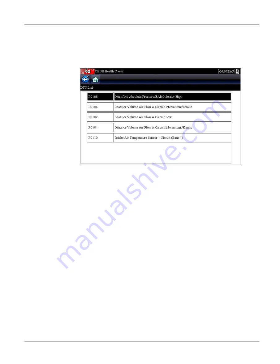
The Code Check displays stored emission related generic DTCs reported by the ECM. Selecting 
this option opens a submenu with two choices: Codes and Pending Codes. Select an option to 
display the code list.

Figure 6-2 

Sample code list

Codes

The Codes option displays a list of current emission related DTCs.

OBD-II/EOBD Codes have a priority according to their emission severity, with higher priority codes 
overwriting lower priority codes. The priority of the code determines the illumination of the MIL and 
the code erase procedure. Vehicle manufacturers have implemented the ranking differently, so 
there are differences between makes.

Pending Codes

The purpose of this service is to enable the scan tool to obtain “pending” or maturing diagnostic 
trouble codes. These are codes whose setting conditions were met during the last drive cycle, but 
need to be met on two or more consecutive drive cycles before the DTC actually sets.

The intended use of this service is to assist the service technician following a vehicle repair and 
code clearing procedure by reporting test results after a single drive cycle.

If a test failed during the drive cycle, the DTC associated with that test is reported. If the 
pending fault does not occur again within 40 to 80 warm-up cycles, the fault is automatically 
cleared from memory.

Test results reported by this service do not necessarily indicate a faulty component or system. 
If test results indicate another failure after additional driving, then a DTC is set to indicate a 
faulty component or system, and the MIL is illuminated.

Refer to and the 

Global OBD Vehicle Communication Software Manual

 for additional information.

Содержание SOLUS Ultra

Страница 1: ...User Manual EAZ0075L19B Rev B 1 H 18 UK ...

Страница 2: ...p on reserves the right to make changes at any time without notice IMPORTANT Before operating or maintaining this unit please read this manual carefully paying extra attention to the safety warnings and precautions Software License Information Use of Software is governed by the terms and conditions of the End User License Agreement The diagnostic tool should not be initially operated until the End...

Страница 3: ... specific training videos are available on our website Follow along and learn the basics of diagnostic tool operation with our free training videos Videos are product specific and are available at http diagnostics snapon co uk Click on the Training and Support tab select Diagnostic Tools then select the applicable diagnostic tool and then select See Quick Tips NOTE i Sample titles are listed below...

Страница 4: ... select See Quick Tips https www youtube com user snaponscanner videos Use the search function to find a title or enter Diagnostic Quick Tips in the search field to see a list of all applicable titles NOTE i URL links above and titles listed below are subject to change and may not be available in all markets A sample list of titles are listed below other titles may be available Some videos may not...

Страница 5: ...es Ford Battery Monitor System Oil Specs Service Light Resets Ford Coil Current RFI Test Scope PID Trigger Functions Scanner Ford Flash Reprogramming Piezo Injectors Signature Test Ford Misfire Monitor Neutral Profile Correction Scanner Relative Compression Test Scope Ford PATS Key Programming ShopStream Connect Data Manipulation Ford Relative Compression Test ShopStream Connect Software Updates F...

Страница 6: ...wer Sources 11 Internal Battery Pack 11 AC Power Supply 12 Vehicle Power 12 The Stand 12 Chapter 3 Getting Started 13 Powering Up 13 Home Screen 13 Home Screen Buttons 14 The Demonstration Program 15 Powering Down 15 Emergency Shutdown 15 Chapter 4 Navigation 16 Screen Layout 16 Title Bar 16 Toolbar 17 Main Body 18 Screen Messages 19 Loading and Connecting Messages 19 Confirmation Messages 19 Warn...

Страница 7: ...hicles and Data 49 Vehicle History 49 View Saved Data 50 Viewing Codes and Code Scan Results 51 Delete Saved Data 52 Chapter 8 Tools 53 Tools Menu 53 Connect to PC 53 Configure Shortcut Key 54 System Information 55 Settings 55 Chapter 9 Maintenance 63 Cleaning and Inspecting the Scan Tool 63 Cleaning the Touch Screen 63 Battery Service 63 Battery Safety Guidelines 64 Replacing the Battery Pack 64 ...

Страница 8: ...propriate and acceptable manner that does not endanger your safety the safety of others in the work area the equipment being used or the vehicle being tested It is assumed that the operator has a thorough understanding of vehicle systems before using this product Understanding of these system principles and operating theories is necessary for competent safe and accurate use of this instrument Befo...

Страница 9: ...ssible consequences of not avoiding the hazard An icon when present gives a graphical description of the potential hazard Example 8 3 Risk of unexpected vehicle movement Block drive wheels before performing a test with engine running A moving vehicle can cause injury Important Safety Instructions For a complete list of safety messages refer to the accompanying safety manual SAVE THESE INSTRUCTIONS...

Страница 10: ...sed in procedures to highlight selectable items such as buttons and menu options Example Press the OK button 1 1 2 Symbols Different types of arrows are used The greater than arrow indicates an abbreviated set of selection instructions Example Select Tools Connect to PC The example statement abbreviates the following procedure 1 Select Tools from the home screen 2 Highlight Connect to PC on the To...

Страница 11: ...wing messages are used Notes A NOTE provides helpful information such as additional explanations tips and comments Example NOTE i For additional information refer to Important IMPORTANT indicates a situation which if not avoided may result in damage to the test equipment or vehicle Example IMPORTANT Do not disconnect the data cable while the Scanner is communicating with the ECM 1 1 5 Procedures A...

Страница 12: ...parameters on a single screen and also includes an extensive database of vehicle specific troubleshooting information This chapter describes the construction of the scan tool and addresses the use of the basic hardware controls and features in the following sections Functional Description on page 7 Technical Specifications on page 9 Control Keys on page 10 Power Sources on page 11 The Stand on pag...

Страница 13: ...ply Input Port 2 Battery Status Indicator LED light emitting diode 3 Mini USB Client Port 4 Micro secure digital uSD Card Port 5 Data Cable Port Figure 2 2 Top view 1 Collapsible Stand closed 2 Battery Compartment Cover Figure 2 3 Back view 5 4 3 2 1 1 2 ...

Страница 14: ... 28V DC Dimensions Width 11 2 inches 285 0 mm Height 5 98 inches 151 8 mm Depth 2 0 inches 50 9 mm Weight including battery pack 2 6 lbs 1 18 kg Operating Temperature Range ambient At 0 to 90 relative humidity non condensing 32 to 113 F 0 to 45 C Storage Temperature ambient At 0 to 70 relative humidity non condensing 4 to 140 F 20 to 60 C Environmental Conditions This product is intended for indoo...

Страница 15: ...ys move the cursor or highlight in their respective directions Up b Down d Left e Right c Key Icon Description Accept Yes Selects a menu or program advances to the next screen or provides a yes answer to a question on the screen Directional Arrows Moves the highlight on the display screen up down left and right as indicated by the arrows Cancel No Exits a menu or program returns to the previous sc...

Страница 16: ...ollowing sources Internal Battery Pack AC Power Supply Vehicle Power 2 4 1 Internal Battery Pack The scan tool can be powered from the internal rechargeable battery pack A fully charged standard battery pack provides sufficient power for about 2 hours of continuous operation A multi color LED on top of the unit Figure 2 2 illuminates to indicate battery status Interpret the LED as follows Green in...

Страница 17: ...ck the green LED on the data cable see Cables on page 23 for additional information If the LED is not illuminated suspect a problem on the DLC power circuit Certain vehicles do not provide vehicle power on the DLC For these applications a separate cable adapter and power cable are needed to power the unit Optional data cable adapters are available for a number of vehicle manufacturers Contact your...

Страница 18: ... of the unit to switch the scan tool on The system boots up then opens the Home screen Figure 3 1 3 2 Home Screen The main body of the Home screen has four selectable buttons one for each of the primary scan tool functions These are explained briefly in the next section and discussed in detail in the Navigation chapter 1 Titlebar 2 Main Body Figure 3 1 Sample Home screen Scanner OBD II EOBD Previo...

Страница 19: ... power is being supplied by the internal battery pack Indicates the internal battery pack is weak and needs recharging Indicates power is being supplied by the AC power supply Indicates power is being supplied by the vehicle Indicates the scan tool is actively communicating with a vehicle Table 3 2 Home screen buttons Name Button Description Scanner Open a list of vehicle manufacturers to begin th...

Страница 20: ...screen A systems menu which shows all of the systems available for testing displays 7 Select from any of the systems listed then select from the submenus NOTE i There is also an OBD II EOBD demonstration select OBD Training Mode in OBD II EOBD 3 3 Powering Down Use the Power key to turn the scan tool off IMPORTANT All vehicle communication must be terminated before shutting down the scan tool A wa...

Страница 21: ...screen provides basic information about current tool operating conditions Title bar options vary depending upon vehicle make and model what test is being performed or what menu is selected Title bar information may include The identification ID of the test vehicle The name of the active menu or database A power source indicator A vehicle communication indicator Depending upon what is being display...

Страница 22: ...ar Home Returns to the Home screen This button is always alongside the Back button on the left side of the toolbar Pause Indicates live data from the vehicle is being displayed Record Indicates the data being displayed is paused when reviewing a movie Clear Erases all the data in the buffer and begins a new recording Selecting opens a confirmation message Sort Determines the order in which the dat...

Страница 23: ... 4 2 Sample scroll bar Tools Opens the tools menu which allows you to adjust basic tool settings Previous Frame Moves back one frame at a time when viewing recorded or paused data Hold the button down to keep moving back through the data Next Frame Moves forward one frame at a time when viewing recorded or paused data Hold the button down to keep moving forward through the data Back 10 Frames Move...

Страница 24: ...ng an internal operation such as loading a database initiating a test or establishing communications with the vehicle The message automatically clears once the internal operation is complete 4 2 2 Confirmation Messages Confirmation messages inform you when you are about to perform an action that cannot be reversed or when an action that requires your confirmation to continue has been initiated Whe...

Страница 25: ... provided by the ECM of the vehicle being tested Therefore certain attributes of the test vehicle must be entered into the scan tool to ensure the data displays correctly This vehicle identification sequence is menu driven simply follow the screen prompts and make a series of choices Each selection advances you to the next screen Exact procedures may vary somewhat by the make model and year of the...

Страница 26: ... the required information A confirmation screen displays once all the required data has been entered Figure 5 2 Figure 5 2 Sample confirmation dialog box 4 From the Confirm Vehicle screen select a OK to continue b Cancel to return to the engine list When Yes is selected list of systems available for testing on the identified vehicle displays 5 Select a system from the list to continue Figure 5 3 F...

Страница 27: ...ic OBD II or EOBD tests see OBD II EOBD on page 40 for additional information System ID Mode allows you to begin the vehicle identification by first selecting the system to be tested Selecting opens a menu of manufacturers that support this mode Select by Database allows you to begin the vehicle identification by first selecting which manufacturer database to load Selecting opens a menu of availab...

Страница 28: ...rcuit or a blown data cable fuse All OBD II EOBD vehicles have vehicle battery power B available on the DLC The optional auxiliary power cable supplies power for testing non OBD II EOBD models that do not have B available on the diagnostic connector The optional cable and adapters are required for testing non OBD II EOBD models z To connect the data cable to the vehicle 1 Follow the on screen inst...

Страница 29: ...icle a Scanner Main menu which lists available tests displays Figure 5 5 Sample Scanner Main menu Main menu options vary slightly by the year make and model of the test vehicle The main menu may include Data Display displays data parameter information from the vehicle control module Selecting may open a submenu of viewing options Codes Menu displays diagnostic trouble code DTC records from the veh...

Страница 30: ...as Codes Codes Menu Codes Only Codes No Data Service Codes or something similar on the menu Selecting opens a list of data parameter viewing options that includes Display Codes Clear Codes Freeze Frame Failure Records DTC Status Display Codes Selecting either opens a list of diagnostic trouble codes DTCs stored in the selected electronic control module ECM or a submenu of DTC viewing options Subme...

Страница 31: ...A codes cleared message displays once the operation is complete 3 Select Continue to return to the Codes Menu Freeze Frame Failure Records This selection displays the DTC that was set along with corresponding data when the ECM commanded the malfunction indicator lamp MIL to turn on Code Scan One of the benefits of performing a code scan is that you can quickly show your customer diagnostic related...

Страница 32: ...unknown issues that may be related to the present symptoms Performing pre and post scans also allows you to record in report format the pre condition of the vehicle and compare the post scan after work is complete to confirm the repairs were completed properly Pre and post scan is required by some manufacturers for pre and post collision work as well as by some insurance companies Figure 5 7 Typic...

Страница 33: ...e following Code Scan related control icons are used The following results are displayed progressively as the modules are scanned The total number of systems modules detected Figure 5 8 Figure 5 8 Code Scan systems analyzed result total A list of all the systems analyzed with DTCs totals A categorized system list with DTC totals is displayed in the order they are scanned To view the main menu for ...

Страница 34: ...n the diagnostic tool See View Saved Data on page 50 Using ShopStream Connect See ShopStream Connect on page 66 Printing the Code Scan Report The vehicle system report can also be customized and printed using ShopStream Connect See Printing the Code Scan Report on page 70 Clear All Codes Read by Code Scan Selecting Clear All Codes Read by Code Scan erases all DTCs from all vehicle system modules t...

Страница 35: ...ue or state Parameters are listed in the order in which they are transmitted by the ECM so there will be variation between makes and models Three parameters can be locked or fixed at the top of the list so they do not change as you scroll through the parameter list in the lower frame Use the Lock Unlock button on the toolbar to select which parameters are fixed see Locking Parameters on page 34 Pa...

Страница 36: ... 4 Frame counter current frame total frames 5 Position indicator Figure 5 11 Sample paused frame of data 2 Scroll to review the data in the frame 3 To switch frames touch Previous Frame or Next Frame Each button touch moves one frame in the selected direction z To resume collecting data Touch the Record button The display changes to live data and the Pause icon is shown on the toolbar NOTE i The S...

Страница 37: ...ch specific parameters display Minimizing the number of parameters on the data list allows you to focus on any suspicious or symptom specific data parameters You can add or remove most parameters from the list Certain vital parameters cannot be removed These appear in gray at the top of the list along with a lock icon and cannot be selected IMPORTANT Limiting the number of parameters that displays...

Страница 38: ... Use the Select All button to display the complete list Use the Deselect All button to remove all of the highlights Use the Cancel button to return to the data display 3 Select OK to display the updated data list Changing Screen Views Selecting the Graph button opens a dropdown menu of options PID List 1 Graph 2 Graph 4 Graph The PID parameter identification List view is a 2 column display with th...

Страница 39: ...tencies Locked parameters display as the top frames on the main body of the display screen as well as at their usual position in the data list Figure 5 13 In PID List mode a lock icon appears to the left of the parameter name to indicate it is locked z To lock parameters 1 Highlight the parameter to be locked 2 Tap the Lock Unlock button on the toolbar to lock it A copy of the locked parameter is ...

Страница 40: ...roblem or to verify a repair during a road test Saved files also provide documentation that helps you explain driveability problems to your customers A number of data movies can be stored which can later be opened by selecting the Previous Vehicles and Data button on the home screen Saved files can also be downloaded from the scan tool to a personal computer PC through the Mini USB port Once conne...

Страница 41: ... for the highlighted parameter Arm Trigger activates the scan tool to capture an event when the signal crosses a threshold Clear All Triggers deletes all previously set trigger levels If triggers are set the menu options are Clear Trigger deletes set trigger levels for the highlighted parameter Disarm Trigger de activates event capture capability Clear All Triggers deletes all previously set trigg...

Страница 42: ... to the live data view and the trigger points appear as horizontal lines across the designated parameter graphs Repeat this procedure to establish trigger points for other parameters if desired Once armed any data points that register outside of your set conditions pause data collection and save a recording NOTE i Only three parameters can have trigger levels set at one time but only one of the co...

Страница 43: ...s by make and model Selecting a menu option either activates the test or opens a submenu of additional choices Follow all screen instructions while performing tests How and what information is presented on the screen varies according to the type of test being performed Some toggle and variable control tests display functional test controls at the top of the screen with datastream information below...

Страница 44: ...ues are provided for comparison Certain live data parameter values display directly within the tip when performing Troubleshooter tests and procedures A tip may also contain a hyperlink to a another test or procedure or a supplemental operation such as Clear Codes Hyperlinks are shown in blue and tapping them opens the link 5 4 Exiting the Scanner The Scanner remains open as long as there is an ac...

Страница 45: ...t are not included in the Scanner databases OBD II EOBD is a Scanner function and the scan tool must be connected to the test vehicle and communicating with the display device Keep in mind this function provides generic OBD II information only Select from the Vehicle Manufacturers Menu for enhanced OBD II functions Selecting OBD II EOBD on the Home screen opens a menu with two options OBD II Healt...

Страница 46: ...can tool to obtain pending or maturing diagnostic trouble codes These are codes whose setting conditions were met during the last drive cycle but need to be met on two or more consecutive drive cycles before the DTC actually sets The intended use of this service is to assist the service technician following a vehicle repair and code clearing procedure by reporting test results after a single drive...

Страница 47: ...I EOBD system checks the status of emission related subsystems by running continuous or periodic tests Two viewing options are available once Readiness Monitors is selected Monitors Complete Since DTC Cleared displays the status of all monitors that have run since the last time DTC were erased from PCM memory Monitors Complete This Cycle displays the status of the monitors that ran during the curr...

Страница 48: ...play 4 Select Continue Information on where to locate the vehicle diagnostic connector displays Figure 6 4 Sample diagnostic connector location 5 Select Continue to return to the System menu 6 2 OBD Diagnose Selecting OBD Diagnose opens a menu with the following options Start Communication initiates a test session Select Communication Protocol establishes which communication protocol to use Connec...

Страница 49: ...y control modules were detected which ECM is communicating and which communication protocol is being used Figure 6 5 Figure 6 5 Sample protocol information screen 4 Select Continue A Select Service menu of available tests displays options include Readiness Monitors MIL Status Display Current Data 01 Clear Emissions Related Data 4 Display Freeze Frame Data 02 Display Trouble Codes 03 Display Test P...

Страница 50: ... commanded the MIL on and the distance driven while the MIL is on if supported can also be displayed It is also possible to save the MIL Status report 01 Display Current Data Use this item to display the current emission related data from the selected electronic control module ECM of the vehicle Displayed data includes analog inputs and outputs digital inputs and outputs and system status informat...

Страница 51: ...screen updates several times as ECM memory is erased then a data has been cleared message displays Select Continue to return to the Select Service menu 05 06 07 Display Test param Results This selection opens a submenu of test parameters and test results form various sensors monitor test results and a record of DTCs detected during the last drive cycle The menu includes 05 Oxygen Sensor Monitoring...

Страница 52: ...ECM The purpose of this service is to allow the Scanner to control the operation of an onboard system test or component Select a test and follow the on screen instructions 09 Read Vehicle Identification The purpose of this service is to enable the Scanner to request and display vehicle specific information such as the vehicle identification number VIN the calibration identification and the calibra...

Страница 53: ...t Communication Protocol A communication protocol is a standardized way of data communication between an ECM and a scan tool Global OBD may use the following communication protocols ISO 9141 2 K LINE SAE J1850 PWM Pulse Width Modulation SAE J1850 VPW Variable Pulse Width ISO 14230 4 Keyword Protocol 2000 SAE J2284 ISO 15765 4 CAN Touch Select Communication Protocol to open a menu of options Figure...

Страница 54: ...hen performing a retest after repairs have been made The oldest vehicle record is deleted when a new vehicle is identified once there are twenty five vehicles on file Figure 7 1 Sample vehicle history list z To select from the vehicle History 1 Select Previous Vehicles and Data from the Home screen 2 Select Vehicle History from the menu A list of up to 25 previously tested vehicles displays Each v...

Страница 55: ...e ID characteristics are included in the listings as well Figure 7 2 Sample saved data list Saved files can either be opened directly on the scan tool or downloaded to a personal computer and opened using ShopStream Connect software z To review a movie 1 Select Previous Vehicles and Data from the Home screen 2 Select View Saved Data from the menu 3 Select a movie from the list of saved files The m...

Страница 56: ...results are saved they are saved in XML file format Figure 7 3 Figure 7 3 Typical Code Results XML file The saved XML file s can be viewed using these methods On the diagnostic tool See Viewing Code Results on the Diagnostic Tool on page 52 In report format using ShopStream Connect see Printing the Code Scan Report on page 70 ...

Страница 57: ...ile 1 Select Previous Vehicles and Data from the Home screen 2 Select Delete Saved Data from the menu A list of saved files displays NOTE i The Select Deselect and Select All Deselect All buttons become available on the toolbar so that you can either delete individual files or clear the entire memory buffer all art once 3 Select a file from the list and a confirmation message displays 4 Select an ...

Страница 58: ...n use to display configuration information for your scan tool Settings use to configure certain characteristics of the scan tool 8 1 1 Connect to PC Connect to PC allows you to transfer saved data files on your diagnostic tool to your personal computer using a USB cable The optional ShopStream Connect PC software allows you to view print and save data files on your PC In addition you can download ...

Страница 59: ...ighest then returns to the lowest setting and continuously repeats Save Screen takes a snapshot of the current screen as either a bitmap or jpeg image A snapshot includes the visible screen image only Save Movie saves a recording of a number of frames of data buffered data plus data transmitted after triggering for each available parameter Show Shortcut Menu opens the Configure Shortcuts menu when...

Страница 60: ... 3 Sample system information screen 3 Select Back on the toolbar or press the N X key to return to the options menu 8 1 4 Settings This Tools selection allows you to adjust certain basic diagnostic tool functions to your personal preferences Selecting opens an additional menu that offers the following System Settings on page 55 Configure Scanner on page 61 Configure Units on page 62 System Setting...

Страница 61: ...ude Time Zone on page 59 sets the internal clock to the local time standard Clock Settings on page 59 sets the time on the internal clock Daylight Savings Time on page 60 configures the clock for Daylight Savings Time Time Format on page 60 switches the time displays between a 12 or 24 hour clock Date Format on page 61 configures how the month date and year displays Brightness Selecting this optio...

Страница 62: ...nd and Night Theme black background Make a selection and a please wait message momentarily displays followed by the Home screen The new toolbar setting is now active Figure 8 5 Sample Night Theme menu screen High Contrast Toolbar This option allows you to switch to a high contrast toolbar This toolbar features black and white buttons with crisp graphics that are easier to see in poor lighting cond...

Страница 63: ...ither the Settings menu or the Home screen Backlight Time This option allows you to configure how long the screen backlight remains on when the tool is inactive The following choices are available Always On 15 Seconds 30 Seconds 45 Seconds 60 Seconds Tap the menu item desired or scroll with the keypad and Press Y a to make a selection Select Back or Home on the toolbar to return to either the Sett...

Страница 64: ...s in process serious damage to the unit may result Time Zone This option opens a menu of time zone settings Scroll to highlight then select the local time zone The display returns to the Settings menu once a time zone is selected Clock Settings This option opens a window for resetting the time on the real time clock z To set the clock 1 Select Tools from the Home screen to open the menu 2 Select S...

Страница 65: ...ayed 7 Tap the Back on the toolbar or press the Y a on the keypad to close the Clock Settings window and return to the Settings menu Daylight Savings Time This option opens a menu to configure the internal clock for Daylight Savings Time Choose from ON sets the clock for Daylight Savings time OFF sets the clock for standard time Make either selection then tap the Back button or press the N X key t...

Страница 66: ... Scales are the graduations and values that display on the horizontal axis at the base of the parameter graphs The waveform to fill the entire graph area with scales switched off Figure 8 9 Sample scanner screen with scales hidden z To switch scanner scales 1 Select Tools from the Home screen 2 Select Settings from the Tools and Setup menu 3 Select Configure Scanner from the Settings menu 4 Highli...

Страница 67: ... Figure 8 10 Sample Configure Units menu z To change the units setup 1 Select Tools from the Home screen to open the menu 2 Select Configure Units to open the menu 3 Select an item from the Configure Units menu Temperature Vehicle Speed Pressure Air Scanner Pressure Other Scanner 4 Select a setting from the listed choices 5 Select Back on the toolbar or press the N X key to return to the options m...

Страница 68: ...s or automotive chemicals on the touch screen 9 2 Battery Service Follow all safety guidelines when handling the battery pack 8 3 Risk of electric shock Prior to recycling the battery pack protect exposed terminals with heavy insulating tape to prevent shorting Disconnect all test leads and turn diagnostic tools off before removing the battery pack Do not attempt to disassemble the battery pack or...

Страница 69: ...g to prevent loss of capacity due to self discharging If long term storage of the battery pack is necessary it should be stored in a in cool dry well ventilated place with a 30 to 75 percent state of charge to prevent loss of characteristics To prolong the life of your battery power off the unit when not in use The scan tool has a built in charger that recharges the battery on demand whenever it i...

Страница 70: ...contain recyclable materials If shipping is required ship the battery pack to a recyling facility in accordance with local national and international regulations For additional information contact United Kingdom Electrical Waste Recycling Company at http www electricalwaste com Products bearing the WEEE logo Figure 9 2 are subject to European Union regulations Figure 9 2 sample WEEE logo NOTE i Al...

Страница 71: ...to share the data in a report format with vehicle owners or other technicians Add or edit notes and comments to diagnostic tool data files Download and install diagnostic tool software updates and upgrades The ShopStream Connect SSC software is available free of charge at ShopStream Connect https www snapon com diagnostics UK Diagnostics ShopStreamConnect htm 10 1 Using SSC Connecting to your PC z...

Страница 72: ...m the menu bar to save your notes NOTE Not all file types allow notes the Notes window will be grayed out when a file type that does not support notes is highlighted Some image files may display notes for reference purposes the notes are grayed out and not editable 2 File directory structure displays the file directory structure of your PC in standard Windows format and shows any connected diagnos...

Страница 73: ...r DataViewer SSC allows you to view data files recorded with your diagnostic tool on your PC When a Scanner data file is selected it opens and displays in the Scanner DataViewer Figure 10 3 Scanner DataViewer allows you play the data file and custom configure the data in a number of ways Figure 10 3 1 Menu bar 2 Display toolbar 3 Graph display 4 Properties icon 5 Vertical Scroll bar 6 Zoom control...

Страница 74: ...iagnostic tool with your PC NOTE i File extension types vary depending on the diagnostic tool Not all the file extensions described here may be available on your diagnostic tool Figure 10 4 1 Exit closes the Image Viewer 2 Print prints the image 3 Print Preview allows the image to be previewed before printing 4 Captured Screen Image 4 3 1 2 ...

Страница 75: ...opened using ShopStream Connect To print the Code Scan Report using ShopStream Connect 1 Double click the code scan XML file from the file list to open the report Figure 10 5 in the Code Scan Viewer Figure 10 6 Figure 10 5 2 Select Print or Print Preview from the Code Scan Viewer menu to print or preview the report Figure 10 6 Figure 10 6 Diagnostic Tool ...

Страница 76: ...provided as necessary to update installed software When your diagnostic tool is connected to a PC using SSC the SSC software will automatically check for updates and if an update is available it will provide installation instructions Follow the screen prompts to accept download and install the software NOTE i To receive updates or upgrades SSC software must be installed on your PC and have connect...

Страница 77: ...e ShopStream Connect User Manual from our website https www snapon com diagnostics uk User Manuals htm ShopStream Connect will now check for updates for the following Do you wish to continue SOLUSULTRA The following update is available for SOLUSULTRA Version 3 3 1 11769 US Size 38 96 MB SOLUSULTRA 13 4 1 After update us complete if direct connected unplug USB cable if using Compact Flash CF insert...

Страница 78: ...owledges your acceptance of the End User License Agreement The Snap on Incorporated Software End User License Agreement is available at https eula snapon com diagnostics To Accept at the screen prompt Figure 10 10 click the checkbox on the left side of the window and then select Agree and Continue The software will be installed automatically Figure 10 10 below represents a typical EULA acceptance ...

Отзывы: