background image

20K 2-Post Lift 

Installation, Operation and Maintenance 


Page 4 


Rev. 11/10/2021


EAZ0080V85A 

R

ECEIVING


The shipment should be thoroughly inspected as soon 
as  it  is  received.  The  signed  bill  of  lading  is 
acknowledgement  by  the  carrier  of  receipt  in  good 
condition of shipment covered by our invoice. 
If any of the goods called for on this bill of lading are 
shorted  or  damaged,  do  not  accept  them  until  the 
carrier  makes  a  notation  on  the  freight  bill  of  the 
shorted  or  damaged  goods.  Do  this  for  your  own 
protection. 
NOTIFY 

Snap-on  Equipment

  AT  ONCE  if  any 

hidden loss or damage is discovered after receipt. 
IT  IS  DIFFICULT  TO  COLLECT  FOR  LOSS  OR 
DAMAGE AFTER YOU HAVE GIVEN THE CARRIER 
A CLEAR RECEIPT. 
File your claim with 

Snap-on Equipment


promptly. 

Support  your  claim  with  copies  of  the  bill  of  lading, 
freight bill, and photographs, if available. 


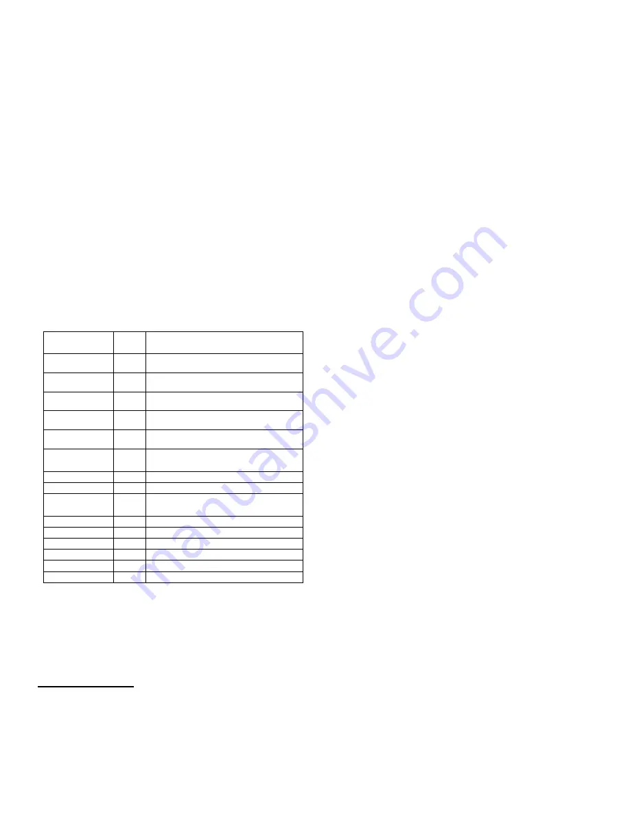
Component Packing List 


PART # 

QTY/ 

LIFT 

DESCRIPTION 

12320-P 

P

OWER 

C

OLUMN 

A

SSAY


12320-

!


I

DLER 

C

OLUMN 

A

SS

Y


12300 

O

VERHEAD 

P

ACK


CL20-HW 

H

ARDWARE 

B

OX


12006 

A

RM 

P

ACK


12311-0 

C

OLUMN 

E

XT

.


A

SSY 

(14’-6”


O.A.


H

T

.) 

12311-2 

C

OLUMN 

E

XT

.


A

SSY 

(16’-6”


O.A.


H

T

.) 

12074 

O

VERHEAD 

S

HUTOFF 

B

AR 

A

SS

Y


B2064-01 

O

VERHEAD LIMIT 

S

WITCH


12302-0 

S

YNC

.


C

ABLE 

P

ACK 

(14’-6”) 

12302-2 

S

YNC

.


C

ABLE 

P

ACK 

(16’-6”) 

B12069 

A

DAPTER 

E

XTENSION 

(4”) 

B12068 

A

DAPTER 

E

XTENSION 

(8”) 

12091 

A

DAPTER 

R

ACK


12093 

A

RM 

R

ESTRAINT 

A

SSEMBLY


AB-93178 

P

OWER 

U

NIT 


S

INGLE 

P

HASE


CL16-IOM 

L

ITERATURE 

P

ACK


A

CCEPTED 

O

ILS 


Do  not  use  oils  with  detergents


Hydraulic fluid is not provided with the lift shipment 

-10


wt. 

anti-foam, anti-rust hydraulic / biodegradable oil


-Dexron III ATF 
 

I

NSTALLATION


S

AFETY 

R

EQUIREMENTS FOR 

I

NSTALLATION AND 

S

ERVICE


Refer to ANSI/ALI ALIS (current edition) 

I

MPORTANT

:


Always wear safety glasses while installing lift. 

T

OOLS 

(

MINIMUM REQUIRED

a.  Tape measure, 16ft 

b.  Chalk line 
c.  4ft level 
d.  10” adjustable wrench 
e.  Standard open end wrenches 7/16”, 1/2", 
       (2) 9/16”, (2) 11/16”, 3/4" 
f.  5/16” Hex wrench FF 
g.  Needle nose pliers 
h.  Hammer  drill  with  3/4”  diameter  carbide  tipped 

bits 

i.  2 lb. hammer 
j.  Torque wrench: 150 foot pounds minimum with 1 

1/8” socket 

k.  12 

ft. 

Step 

ladder


l.  Anti-Seize  lubricant  (for  arm  pins  and  foot  pad 

screw threads and stop rings) 

L

AYOUT


Note:  

 This lift can be installed at three different heights 

and three different widths. The Cable adjustment 
for the Height variation will be accommodated by 
the  Lower  Sheave  Bracket.  The  Cable 
adjustment  for  the  Width  variation  will  be 
accommodated  by  the  take-up  tube  in  later 
steps. 


 The height and width must be established before 

beginning,  as  this  will  determine  the  lower 
sheave  position  and  cable  take  up  tubes  to  be 
used.


1)  Once  the  lift  location  has  been  established, 

ensure  that  the  vertical  clearance  and  flooring 
requirements have been met per page 3. 

2)  See 

Fig 1

 for the lift layout. Determine which side 

of  the  bay  that  the  power  unit  will  be  on  and 
identify the column assembly with the power unit 
bracket. Layout the service bay according to the 
architect’s plans or owner’s instructions 

(see Fig. 

1b

). 

Failure  to  install  in  this  orientation  can 

result  in  personal  and  property  damage.   

Be 

certain that the proper conditions exist, see pg. 3. 

L

IFT 

P

REPARATION


3)  With column assemblies lying flat, remove cable 

and hose rolls from inside the column. 

4)  Manually push carriages up enough to unhook the 

cylinder hose from the base plate tabs. Proceed 
with pushing the cylinder and carriage up enough 
to  access  all  three  sheave  locations  on  the 
sheave bracket, see 

Fig 2

.  

Содержание EELS542A

Страница 1: ...enance Manual 20K Two Post Surface Mounted Lift MODELS EELS542A EELS543A EELS745A EELS746A 20 000 LBS CAPACITY 5000 LBS PER ARM Snap on Equipment 309 Exchange Avenue Conway AR 72032 TEL 800 225 5786 I...

Страница 2: ...RIVE ON DIRECTION G TO NEAREST OBSTRUCTION OR NEAREST WALL 19 REF 168 14 0 MIN TO NEAREST OBSTRUCTION 168 14 0 MIN TO NEAREST OBSTRUCTION COLUMN BASE PLATES E REAR OF COLUMN FRONT OF COLUMN D D Fig 1c...

Страница 3: ...l injury LOCATION This lift has been evaluated for indoor use only with an operating ambient temp range of 5 40 C 41 104 F Outdoor installation is prohibited ELECTRICAL REQUIREMENTS For lift installat...

Страница 4: ...ION AND SERVICE Refer to ANSI ALI ALIS current edition IMPORTANT Always wear safety glasses while installing lift TOOLS MINIMUM REQUIRED a Tape measure 16ft b Chalk line c 4ft level d 10 adjustable wr...

Страница 5: ...ight Install the cable on the sheave and slide into place Stack the 3 8 spacer onto the sheave assembly Still holding the sheave assembly slide the pin into place Install the bolt to secure the pin se...

Страница 6: ...a time around each column 18 Raise both carriages 400 lbs ea high enough to drill the two inner anchor holes on each column Measure both carriage heights to ensure they are in the same lock position 1...

Страница 7: ...with the 10mm dia x 55mm Lg clevis pin hairpin cotter Fig 8 Overhead Bracket Idler Side SYNCHRONIZER CABLES 29 Remove Cable Trapping Hardware at the top of each column Fig 9 Route free end of cables c...

Страница 8: ...d fitting off one full turn Again tighten flared fitting finger tight then rotate flared fitting 1 1 2 hex flats 90 deg 31 Mount Power Unit to power column as shown in Fig 11 The mounting hardware 4 5...

Страница 9: ...Side Hose up the column to the lowest available hole of the column extension Insert steel tubing end of the Power Unit Hose into the extension outside in and connect to the tee Leave the assembly han...

Страница 10: ...d Width and Height CL16 2 6 Reduced Height without Reduced Width CL16 2 6 or 12 Reduced Width without Reduced Height CL16 2 6 Reduced Height with 6 or 12 Reduced Width CL16 2 12 Reduced Height CL16 0...

Страница 11: ...the air line to the Idler Column using black wire ties through the double holes in the middle of the column Place the head of the wire tires inside the column Cut the air line to length and attach it...

Страница 12: ...20 Fig 20 Adapter Rack Installation ELECTRICAL See Figure 21 for the following steps 64 Wire tie Limit Switch cord to Overhead hydraulic Hose and Power Unit Hose 65 Connect the Overhead Limit Switch C...

Страница 13: ...rods The cylinders are shipped with a small amount of clear anti corosive lubricant that will be forced out through the wiper when the lift reaches full rise If lubricant is not wiped clean from the c...

Страница 14: ...20K 2 Post Lift Installation Operation and Maintenance Page 14 Rev 11 10 2021 EAZ0080V85A Fig 21 Electrical Wiring Diagram 2 T1 1 L1 3 A1 4 A2 LOAD INPUT Normally Open FIELD CONNECTIONS...

Страница 15: ...t the lift inspectors are qualified and that they are adequately trained in the inspection of the lift The Owner Employer shall establish procedures to periodically maintain the lift in accordance wit...

Страница 16: ...st the stability of the vehicle by attempting to rock the vehicle Check adapters for secure contact with vehicle lift points If the vehicle seems unstable lower the lift and readjust the arms If the v...

Страница 17: ...heck for loose or broken parts Check hydraulic system for fluid leaks Check adapters for damage or excessive wear Replace as required with genuine Snap on Equipment parts Check lock release activation...

Страница 18: ...MS 7 10 7 B2065 3 4 M6 x 14mm PHILLIPS PAN HEAD SCREW 8 B2065 4 4 M6 SERRATED FLANGE HEX NUT 9 B2065 5 1 CLEVIS PIN 10mm x 55 Lg 10 GJY12 3 1 HAIRPIN COTTER 11 12330 24 1 2 13NC HEX FLG HD C S x 1 Lg...

Страница 19: ...20K 2 Post Lift Installation Operation and Maintenance Page 19 Rev 11 10 2021 EAZ0080V85A PARTS BREAKDOWN continued Fig B Lock Power Idler...

Страница 20: ...WASHER 29 37119 2 CLEVIS PIN KIT 30 37120 2 ROD END CLEVIS 31 37026 2 AIR CYLINDER 32 37041 2 SWIVEL ELBOW 1 8 PUSH LOCK 33 12088 2 EXTENSION SPRING 34 37042 2 CYLINDER PIVOT ROD 35 37031 4 5 32 SPEED...

Страница 21: ...1 HYD TEE 54 12308 1 POWER UNIT HOSE ASSEMBLY 55 AB 93178 1 POWER UNIT SINGLE PHASE AD 93178 1 OPTIONA POWER UNIT THREE PHASE 56 31025 1 LINE CLAMP 57 40085 9 1 4 20 HEX FLANGE NUT 58 A2125 5 1 4 20...

Страница 22: ...HEAVE ASSEMBLY 67 CL31020 8 WASHER 68 CL31021 4 1 3 8 RETAINING RING 69 12302 0 1 SYNC CABLE PACK 14 6 O A Ht 12302 2 1 SYNC CABLE PACK 16 6 O A Ht 70 40053 2 1 8 THICK BEARING 71 40774 S 2 SHEAVE SPA...

Страница 23: ...NEEDED 87 12072 4 1 2 13 x 5 8 SOCKET HD C S 88 12084 4 1 2 INTERNAL TOOTH LOCKWASHER 92 12091 2 ADAPTER RACK 93 A1153 4 3 8 16NC x 3 4 Lg HEX FLG HD C S 94 A1154 4 3 8 16NC HEX FLG NUT 95 B12068 2 S...

Страница 24: ...tallation Operation and Maintenance Page 24 Rev 11 10 2021 EAZ0080V85A REVISIONS 08 23 2021 CREATED FOR NEW PRODUCT RELEASE 11 10 2021 CORRECT TO NEAREST OBSTRUCTION DIMENSIONS 01 13 2022 Brief proof...

Отзывы: