COSMOS DRIVER SERIES 3000 - USE AND MAINTENANCE MANUAL
7.2.9.1
Analog controller
In this configuration, the driver receives a reference speed of ±10V from an external device controlling the axes. The
software controller will perform the speed and torque regulation, leaving the position check to the axes board.
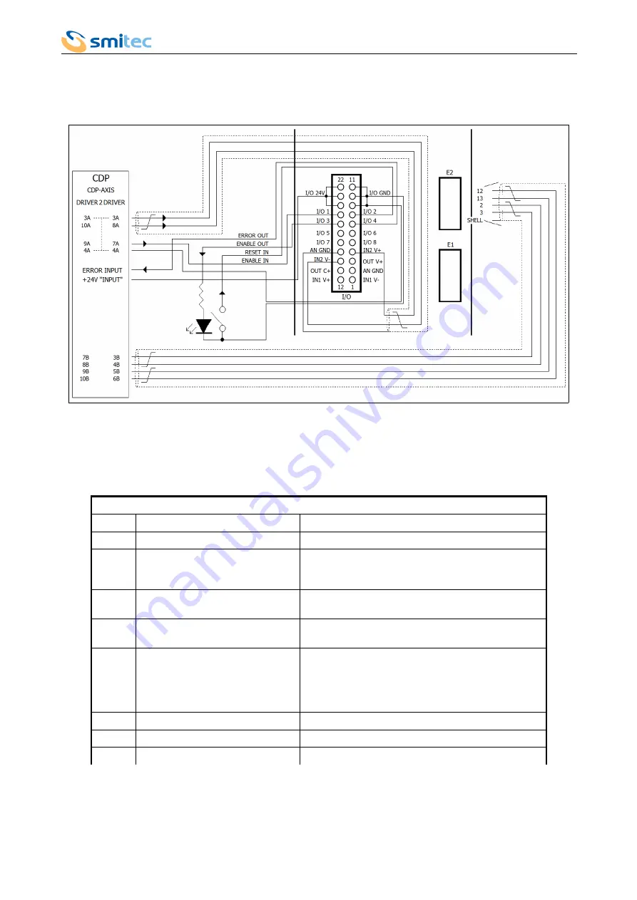
The picture here below shows an example of connection with the “CDP-AXIS” system:
In order to guarantee a correct signal interface, it is necessary to install 2 resistances of 4.7 k Ω 1/4W (KD031056)
between the I/O 24V terminal and the input signals RESET IN and ENABLE IN, as indicated in the electrical diagram. It is
recommended to insulate the resistance terminals, by using the sheaths EK050044.
The following table lists the I/O of the analogue controller:
Digital signals
N° I/O
Signal name
Description
01
ENABLE IN
Enabling signal sent to the driver by the axes board.
02
RESET IN
Reset signal sent to the driver by an external system
(for example a push-button). It is used for cancelling
the error, if any, in the driver.
03
ENABLE OUT
Active output signal - high. It indicates the driver
enabling status (it can be connected to a LED).
04
ERROR OUT
Active output signal – high. It indicates that there is an
error in the driver.
05
READY
Active output signal – high. It becomes active after an
amount of time that can be set from the LCD when the
driver is ready to be enabled. It can be used instead of
ERROR OUT when the enabling request immediately
follows the ERROR OUT disabling.
06
NOT IN USE
-
07
NOT IN USE
-
08
NOT IN USE
-
7.2.9.2
Analogue controller configuration
The configuration consists in setting the parameters concerning the voltage of IN-2 analogue input, so that the speed
reference sent to the driver by the axes external board is interpreted correctly. It is also possible to configure the active
Ver. 1.07
Pag. 73
Interfacciamento scheda “CDP-AXIS”
“CDP-AXIS” board interface


