

VR51-TFO26-A
Installation and Maintenance Manual
Original Instructions
VR51, Two Hand Control Valve
1 Safety Instructions
This manual contains essential information for the protection of users and
others from possible injury and/or equipment damage.
•
Read this manual before using the product, to ensure correct
handling, and read the manuals of related apparatus before use.
•
Keep this manual in a safe place for future reference.
•
These instructions indicate the level of potential hazard by label of
“Caution”, “Warning” or “Danger”, followed by important safety
information which must be carefully followed.
•
To ensure safety of personnel and equipment the safety instructions
in this manual and the product catalogue must be observed, along
with other relevant safety practices.
Caution
Indicates a hazard with a low level of risk, which if not
avoided, could result in minor or moderate injury.
Warning
Indicates a hazard with a medium level of risk, which
if not avoided, could result in death or serious injury.
Danger
Indicates a hazard with a high level of risk, which if
not avoided, will result in death or serious injury.
Warning
•
The compatibility of pneumatic equipment is the responsibility of the
person who designs the pneumatic system or decides its
specifications.
Since the products specified here can be used in various operating
conditions, their compatibility with the specific pneumatic system must
be based on specifications or after analysis and/or tests to meet
specific requirements.
•
Only trained personnel should operate pneumatically operated
machinery and equipment.
Compressed air can be dangerous if an operator is unfamiliar with it.
Assembly, handling or repair of pneumatic systems should be
performed by trained and experienced personnel.
•
Do not service machinery/equipment or attempt to remove
components until safety is confirmed.
1) Inspection and maintenance of machinery/equipment should only
be performed after confirmation of safe locked-out control positions.
2) When equipment is to be removed, confirm the safety process as
mentioned above. Switch off air and electrical supplies and exhaust
all residual compressed air in the system.
3) Before machinery/equipment is re-started, ensure all safety
measures to prevent sudden movement of cylinders etc. (Supply air
into the system gradually to create back pressure, i.e. incorporate a
soft-start valve).
•
Do not use this product outside of the specifications. Contact
SMC if it is to be used in any of the following conditions:
1) Conditions and environments beyond the given specifications, or if
the product is to be used outdoors.
2) Installations in conjunction with atomic energy, railway, air
navigation, vehicles, medical equipment, food and beverage,
recreation equipment, emergency stop circuits, press applications, or
safety equipment.
3) An application which has the possibility of having negative effects
on people, property, or animals, requiring special safety analysis.
Caution
•
Ensure that the air supply system is filtered to 5
μ
m.
2 Specifications
2.1 Specifications
Fluid Air
Operating pressure
0.25 to 1.0 MPa
Proof pressure
1.5 MPa
Ambient and fluid temperature
-5 to 60°C (with no freezing)
Flow characteristics
C[dm3/(s·bar)]
b
Cv
Operating frequency Max
10cpm
Operating frequency Min
Once every 30 days
Vibration & shock resistance
Do not use in a vibration environment
Environment
Indoor use only
P to A
0.3
-
-
A to R
1.0
0.12
0.25
Metric Ø6
Port size
Inch Ø1/4
Applicable tube material
Note)
Nylon, Soft nylon, Polyurethane,
Flame resistant (FR) soft nylon,
FR double layer,
FR double layer polyurethane
Weight 340g
Silencer
Part No.: AN101-01
Accessory
option
Bracket
Part No.: VR51B
Note) In the case of soft nylon or polyurethane tubing, use caution when
the maximum operating pressure of the tubing is used.
2.2 Features
•
When there is a time delay of less than 0.5 seconds between the two
air signal inputs, the VR51 provides an output signal.
•
VR51 output stops when one of the two air signal inputs stops.
•
Two simultaneous air signals resets the output.
2.3 Declaration
of
Conformity
A sample Declaration of conformity (DoC) for this product is shown below.
An actual DoC is supplied with each product.
2 Specifications (Continued)
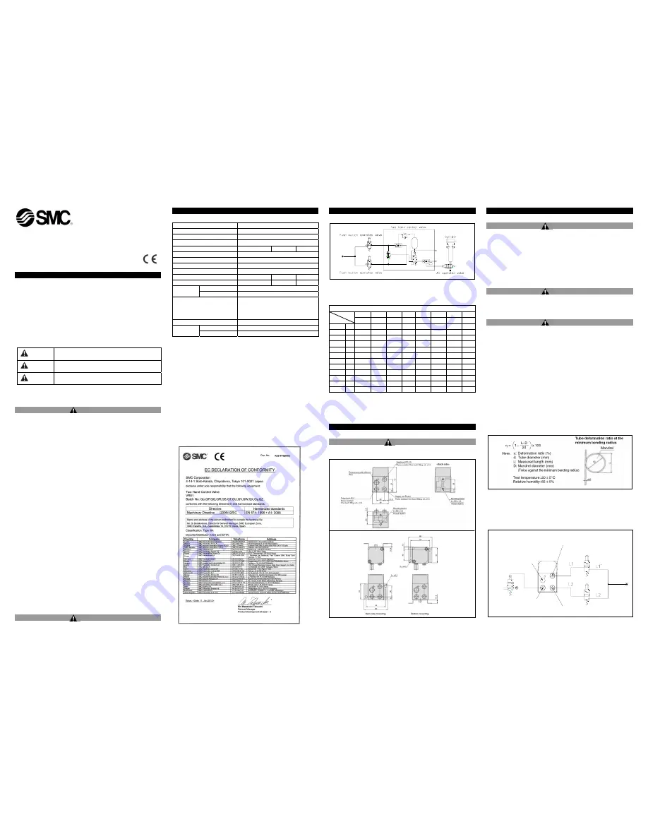
2.4 Typical
Circuit
2.5 Production batch code
The production batch code printed on the label indicates the month and
year of production as shown in the following table:
Production batch codes
2010 2011 2012 … 2021 2022 2023 …
Year
Month
H I J …
Z A B …
Jan O
oo Po Qo … Zo Ao Bo …
Feb P oP PP QP … ZP AP BP …
Mar Q
oQ PQ QQ … ZQ AQ BQ …
Apr R
oR PR QR … ZR AR BR …
May S oS PS QS … ZS AS BS …
Jun T
oT PT QT … ZT AT BT …
Jul U
oU PU QU … ZU AU BU …
Aug V oV PV QV … ZV AV BV …
Sep W
oW PW QW … ZW AW BW …
Oct X
oX PX QX … ZX AX BX …
Nov Y oy Py Qy … Zy Ay By …
Dec Z oZ PZ JZ … ZZ AZ BZ …
Note that lowercase letters are used in some instances.
3 Installation
3.1 Installation
Warning
•
Do not install the product unless the safety instructions have been
read and understood.
Note) Order the silencer separately, see section 2.
3 Installation (Continued)
3.1 Environment
Warning
•
Do not use in an environment where corrosive gases, chemicals, salt
water or steam are present.
•
Do not use in an explosive atmosphere.
•
Do not expose to direct sunlight. Use a suitable protective cover.
•
Do not install in a location subject to vibration or impact. Check the
product specifications.
•
Do not mount in a location exposed to radiant heat.
•
Employ suitable protective measures in locations where there is
contact with oil or welding spatter etc.
Caution
•
Avoid using in places where there is splashing oil, coolant or water.
In addition, avoid using where dust may adhere.
3.2 Piping
Warning
•
Before piping make sure to clean up chips, cutting oil, dust etc.
•
When connecting piping, consult the instruction manual and use
caution to avoid incorrect piping.
•
Connect tubing with a longer length than required to prevent torsion,
stretching or moment loads. Damage of the fittings or flattening, as
well as bursting or releasing of the tubing may occur if the instructions
are not followed.
•
Tubing connected to the VR51 should be used at more than its
minimum bend radius. If used under the minimum bend radius,
bending or flattening of the tubing may occur.
The minimum bend radius is measured in accordance with JIS B
8381-1995.
JIS specifies the tubing deformation ratio measured at the
minimum bend ratio to be 25% or less.
*Except for the TU, TIUB, TUH, TRBU, TAU and TUS series
Tube deformation ratio at the minimum bend radius is obtained by the following formula, based on
tube and mandrel diameter
•
Use the same control valves for each input port.
•
Use tubing of the same length and diameter between the VR51 and
each control actuating device: L2=L1, L2’=L1’.
•
Operate the control valves from the same pressure source.
3.3 Piping Length for Secondary Side
Bracket mounting dimensions
EXHAUST PORT:R(4)
OUTPUT PORT:A(2)
SUPPLY PORT:P2(12)
SUPPLY PORT:P1(11)
Output Port: A(2)
Supply Port: P2(12)
Exhaust Port: R(4)
Supply Port: P1(11)