


-8-
2.2 I/O signal connection
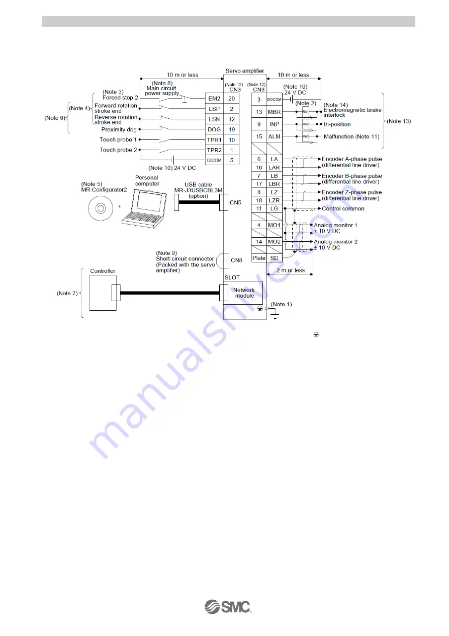
An example of driver input/output signal connection is shown below.
(1)
For sink I/O interface
Note 1. To prevent an electric shock, always connect the protective earth (PE) terminal (marked
) of the driver to the protective
earth (PE) of the cabinet.
2. Connect the diode in the correct direction. If it is connected reversely, the driver will malfunction and will not output signals,
disabling EM2 (Forced stop 2) and other protective circuits.
3. If the upper side does not have forced stop function, always install the forced stop 2 switch (normally closed contact).
4. When starting operation, always turn on EM2 (Forced stop 2), LSP (Forward rotation stroke end) and LSN (Reverse rotation
stroke end). (Normally closed contact)
6. You can change devices of these pins with [Pr. PD03], [Pr. PD05], and [Pr. PD06].
7. For the network connections, refer to
“LECSN-T Operation Manual Chapter 18,19,20”.
8. Configure a circuit to turn off EM2 when the main circuit power is turned off to prevent an unexpected restart of the driver.
9. When not using the STO function, attach the short-circuit connector came with a driver.
10. Supply 24 V DC ± 10% for interfaces from outside. Set the total current capacity to 300 mA. 300 mA is the value applicable
when all I/O signals are used. The current capacity can be decreased by reducing the number of I/O points. The illustration of
the 24 V DC power supply is divided between input signal and output signal for convenience. However, they can be configured
by one.
11. ALM (Malfunction) turns on in normal alarm-free condition. (Normally closed contact)
12. The pins with the same signal name are connected in the driver.
13. You can change devices of these pins with [Pr. PD07], [Pr. PD08], and [Pr. PD09].


