

A
BOUT
THE
EZ S
WITCH
10/100
SMC
-EZ108DT
The EZ Switch 10/100 (SMC-EZ108DT) is an 8-port Fast
Ethernet switch. Its 8 10BASE-T/100BASE-TX ports deliver
dedicated 10/100 Mbps links to each attached LAN
segmentall with conventional cabling and adapters. Auto-
Negotiation is used to select the optimal transmission speed
and communication mode for each connection. With store-
and-forward switching and flow control, maximum data
integrity is always maintained, even under heavy loading. Easy
installation and reliability make this plug-and-play switch an
ideal choice for smooth Fast Ethernet integration.
Features and Benefits
◆
Auto-Negotiation of half or full-duplex on all ports
◆
ANSI/IEEE 802.3u compliance ensures compatibility
with standards-based hubs, switches and cards from
any vendor
◆
Store-and-forward switching ensures error-free
transmission
◆
Half- and full-duplex flow control prevents packets
from being dropped under heavy loading
◆
Plug and play
◆
Built-in wiring crossovers on all ports allow
connections to servers and workstations to be made
with straight-through cabling
◆
At-a-glance LEDs for port and system status
monitoring
◆
Desktop and rack mountable
Front-Panel LEDs
The front panel of the switch provides a link status LED for
each RJ-45 port. In addition, the front panel also contains
status LEDs for at-a-glance system monitoring. The
following table details the functions of the various indicators:
s
D
E
L
s
u
t
a
t
S
h
c
t
i
w
S
d
n
a
t
r
o
P
s
D
E
L
n
o
it
i
d
n
o
C
s
u
t
a
t
S
r
e
w
o
P
n
e
e
r
G
.r
e
w
o
p
g
n
i
v
i
e
c
e
r
si
h
c
ti
w
S
t
c
A
/
k
n
i
L
n
e
e
r
G
n
e
e
w
t
e
b
n
o
it
c
e
n
n
o
c
e
h
t
t
a
h
t
s
e
t
a
c
i
d
n
I
.
d
il
a
v
si
e
c
i
v
e
d
d
e
h
c
a
tt
a
d
n
a
tr
o
p
n
e
e
r
G
g
n
i
h
s
a
l
F
g
n
it
ti
m
s
n
a
rt
si
h
c
ti
w
s
e
h
t
t
a
h
t
s
e
t
a
c
i
d
n
I
.
a
t
a
d
g
n
i
v
i
e
c
e
r
r
o
M
0
0
1
n
e
e
r
G
t
a
g
n
it
a
r
e
p
o
si
tr
o
p
e
h
t
t
a
h
t
s
e
t
a
c
i
d
n
I
.s
p
b
M
0
0
1
X
D
F
n
e
e
r
G
n
i
g
n
it
a
r
e
p
o
si
tr
o
p
e
h
t
t
a
h
t
s
e
t
a
c
i
d
n
I
.
e
d
o
m
x
e
l
p
u
d
-l
l
u
f
n
e
e
r
G
g
n
i
h
s
a
l
F
e
h
t
n
o
d
e
r
u
c
c
o
n
o
is
il
l
o
c
a
s
e
t
a
c
i
d
n
I
-f
l
a
h
n
i
g
n
it
a
r
e
p
o
n
e
h
w
t
n
e
m
g
e
s
tr
o
p
.
e
d
o
m
x
e
l
p
u
d
Front-Panel Ports
The front-panel ports are dual-speed RJ-45 ports with built-in
wiring crossovers. PCs can be connected to these ports with
straight-through cable. Each port supports Auto-Negotiation,
so the optimum communication mode (half or full duplex) and
data rate (10 Mbps or 100 Mbps) are selected automatically.
Port 8 on the switch doubles as a crossover port and a
straight-through daisy-chain port. The daisy-chain port
makes it convenient to connect straight-through cable
from the EZ Switch 10/100 to a crossover port on
another device.
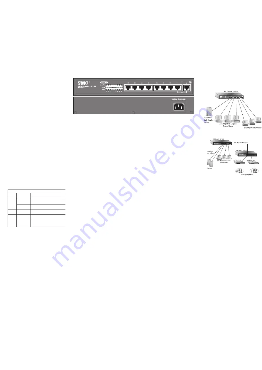
Rear Panel
The AC power receptacle is located on the rear panel of the
switch.
I
NSTALLING
THE
S
WITCH
The EZ Switch 10/100 can be placed on a desktop or shelf,
or installed in a standard 19-inch equipment rack.
Equipment Checklist
After unpacking the EZ Switch 10/100, check the contents of
the box to be sure youve received the following components:
EZ Switch 10/100 SMC-EZ108DT
Appropriate AC power cable
Four adhesive foot pads
SMC Warranty Registration Card
This User Guide
Selecting a Site
Be sure to follow the site selection guidelines below
when choosing a location:
u
Select a suitable location for the switch:
It should be accessible for installing, cabling and
maintaining the switch.
The temperature and humidity should be within
the ranges listed in the specifications.
The status LEDs should be clearly visible.
There should be adequate space (approximately
two inches) on all sides for proper air flow.
u
Before rack mounting the switch, pay particular
attention to the following factors:
Temperature
: Since the temperature within a
rack assembly may be higher than the ambient
room temperature, check that the rack-
environment temperature is within the specified
operating temperature range.
Mechanical Loading
: Do not place any
equipment on top of a rack-mounted switch.
Circuit Overloading
: Be sure that the supply
circuit to the rack assembly is not overloaded.
Grounding
: Rack-mounted equipment should be
properly grounded. Particular attention should
be given to supply connections other than direct
connections to the mains.
u
Make sure twisted-pair cable is always routed away from
power lines, fluorescent lighting fixtures and other sources
of electrical interference such as radios, transmitters, etc.
u
Make sure that a properly grounded power outlet is within
8 feet (2.44 meters) of the switch and is powered from an
independent circuit breaker. As with any equipment, using
a filter or surge suppressor is recommended.
Instructions
1.
Positioning the Switch:
For desktop or shelf mounting,
attach the four adhesive foot pads to the bottom of the
switch. For rack-mounting, attach the mounting brackets to
both sides of the switch with the screws provided, then
install the switch in the rack.
2.
Applying Power:
Plug one end of the power cable into
the power receptacle at the back of the switch, and the
other end into an appropriate electrical outlet. Check the
Power LED to be sure it is on.
Note:
It is not necessary to power off the switch before
connecting or disconnecting any UTP cables, as these
actions
will not
disrupt the operation of other devices
attached to the switch.
3.
Connecting PCs:
Connect each PC to an RJ-45 port
on the switch with a straight-through twisted-pair
cable segment, maximum length 100 meters (328
feet). The EZ Switch 10/100 will support up to 8
PCs. However, if using port 8 be sure to use the
fixed crossover port marked X on the switch.
Note:
If an attached device does not support Auto-
Negotiation, the data rate will be sensed
automatically and the communication mode will
default to half duplex.
4.
Cascading Switches and Other Network Devices:
If you need more ports, connect the daisy-chain
port, marked = on port 8, to a crossover port on
another device. Be sure to use straight-through
twisted-pair cable, maximum length 100 meters (328
feet). Note that if you are using the daisy-chain port
you cannot use the fixed crossover port, marked
X on port 8.
Note:
Alternatively, you can cascade from any
crossover port on the switch to a daisy-chain port
on another device. You may also connect to
crossover ports at both ends if you use a crossover
cable. See the Cable Specifications and
Connectivity Guidelines sections of this guide for
further information.
S
AMPLE
A
PPLICATIONS
Some typical applications for the EZ Switch 10/100 are
illustrated below:
Standalone LAN
High-Speed Switch Links
T
ROUBLESHOOTING
1. Symptom
Power LED does not light after power on.
Probable Causes
Power outlet or power cord may be defective.
Possible Solutions
Check for loose connections.
Check the power outlet by using it for another
device.
Replace the power cord.
2. Symptom
Link LED does not light after connection is made.
Probable Causes
Switch port, network card or cable may be
defective.
Possible Solutions
Check that the switch and attached device are
both powered on.
Be sure the network cable is connected to both
devices.
Verify that Category 5 cable is used for 100 Mps
connections and that the length of any cable
does not exceed 100 meters (328 feet).
Check the network card and cable connections
for defects.
Replace the defective card or cable if necessary.


