
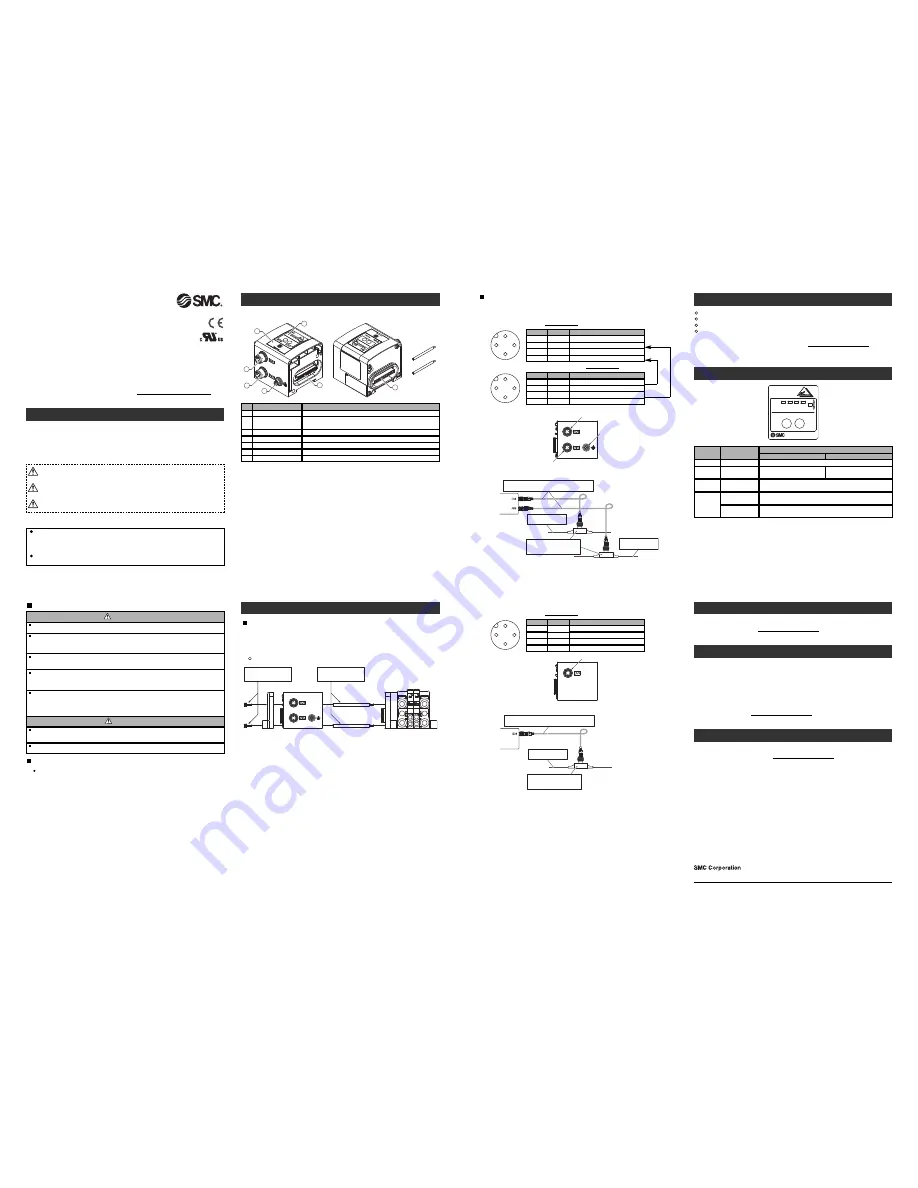
Summary of Product elements
<EX250-SAS3/-SAS5/-SAS7/-SAS9>
ADD
R1
ADD
R2
ADD
RES
S SE
TTIN
G
PWR
AUX
IN
-ERR
COM
-ERR
HOLD
CLEA
R
SW
Tie rod (2 pcs.)
Accessory
1
7
5
6
4
3
AD
DR
1
AD
DR
2
AD
DR
ES
S S
ETT
ING
PW
R
AUX
IN
-ER
R
CO
M
-ER
R
HOL
D
CLE
AR
SW
2
Installation
General instructions on installation and maintenance
Connect valve manifold to the SI unit.
Connectable valve manifolds are the same as for EX250 series SI unit.
Refer to the EX250 series valve manifold section in the valve catalogue for valve
manifold dimensions.
M3 hexagon screw
Tightening torque: 0.6 Nm
Tie rod
Tightening torque: 0.6 Nm
End plate
SI unit
Valve manihold
Addition of input block
•Remove the screws from the end plate to remove the plate.
•Mount the additional tie rods (supplied with the input block).
•Connect additional input block.
•Re-mount the end plate that was removed, and tighten the screws to the specified
tightening torque. (0.6 Nm)
Replacing the SI unit
•Remove the screws from the end plate and release the connection with the valve unit.
•Replace the SI unit. (There is no need to remove the tie rod.)
•Re-mount the input block and end plate that was removed, and tighten the screws to
the specified tightening torque. (0.6 Nm)
Precautions for maintenance
(1)Turn off the power supply completely.
(2)Check that there is no foreign matter inside the unit.
(3)Check that there is no damage and no foreign matter on the gasket.
(4)Tighten the screws to the specified torque.
If the unit is not assembled correctly, this may cause product failure due to foreign
matter such as liquid and dust which may get into the unit.
Connecting cables
Select the appropriate cables to mate with the connectors mounted on the SI unit.
Troubleshooting
Technical documentation giving detailed troubleshooting information can be found
on the SMC website (URL http://www.smcworld.com).
Specifications
Connected load: 24 VDC Solenoid valve with surge voltage suppressor of 1.5 W or less
(manufactured by SMC)
Current consumption of power supply for SI unit operation: 0.1 A max.
Ambient temperature for operation: 5 to 45
o
C
Ambient temperature for storage: -20 to 60
o
C
Pollution degree 3: (UL508)
Technical documentation giving detailed specification information can be found on
the SMC website (URL http://www.smcworld.com).
Outline Dimensions
Technical documentation giving detailed outline dimensions information can be
found on the SMC website (URL http://www.smcworld.com).
Assembly and disassembly of the SI unit
NOTE
When conformity to UL is necessary the SI unit must be used with a UL1310
Class2 power supply.
Safety Instructions
Do not operate the product outside of the specifications.
Do not use for flammable or harmful fluids.
Fire, malfunction, or damage to the product can result.
Verify the specifications before use.
Do not disassemble, modify (including changing the printed circuit board) or repair.
An injury or failure can result.
Do not operate in an atmosphere containing flammable or explosive gases.
Fire or an explosion can result.
This product is not designed to be explosion proof.
If using the product in an interlocking circuit:
•Provide a double interlocking system, for example a mechanical system.
•Check the product regularly for proper operation.
Otherwise malfunction can result, causing an accident.
The following instructions must be followed during maintenance:
•Turn off the power supply.
•Stop the air supply, exhaust the residual pressure and verify that the air is released before performing
maintenance.
Otherwise an injury can result.
Fieldbus device
Operation Manual
EX250 Series for AS-Interface
Thank you for purchasing an SMC EX250 Series Fieldbus device (Hereinafter
referred to as "SI unit" ).
Please read this manual carefully before operating the product and make sure you
understand its capabilities and limitations.
Please keep this manual handy for future reference.
To obtain more detailed information about operating this product,
please refer to the SMC website (URL http://www.smcworld.com) or
contact SMC directly.
Safety Instructions
These safety instructions are intended to prevent hazardous situations and/or
equipment damage.
These instructions indicate the level of potential hazard with the labels of
"Caution", "Warning" or "Danger". They are all important notes for safety and must
be followed in addition to International standards (ISO/IEC) and other safety
regulations.
Warning
Caution
After maintenance is complete, perform appropriate functional inspections.
Stop operation if the equipment does not function properly.
Safety cannot be assured in the case of unexpected malfunction.
CAUTION indicates a hazard with a low level of risk which, if
not avoided, could result in minor or moderate injury.
Caution:
Warning:
Danger:
WARNING indicates a hazard with a medium level of risk
which, if not avoided, could result in death or serious injury.
DANGER indicates a hazard with a high level of risk which, if
not avoided, will result in death or serious injury.
Operator
This operation manual is intended for those who have knowledge of machinery
using pneumatic equipment, and have sufficient knowledge of assembly,
operation and maintenance of such equipment. Only those persons are
allowed to perform assembly, operation and maintenance.
Read and understand this operation manual carefully before assembling,
operating or providing maintenance to the product.
Note: Specifications are subject to change without prior notice and any obligation on the part of the manufacturer.
© 2012 SMC Corporation All Rights Reserved
Akihabara UDX 15F, 4-14-1, Sotokanda, Chiyoda-ku, Tokyo 101-0021, JAPAN
Phone: +81 3-5207-8249 Fax: +81 3-5298-5362
URL http://www.smcworld.com
Provide grounding to assure the safety and noise resistance of the Fieldbus system.
Individual grounding should be provided close to the product with a short cable.
Communication connector
Element
Description
Sends or receives the communication signals via AS-Interface line.
Power supply connector for
output equipment
∗
1
Supplies power to the solenoid valve, output block, etc.
Output block connector
Connects the solenoid valve or output block, etc.
Display window
Displays the status of the SI unit with LEDs.
1
No.
2
4
5
∗
1: Available only for EX250-SAS3/-SAS5.
Switch cover
Sets the address, etc. with the switch inside.
Grounding terminal (FE)
∗
1
Used for grounding.
6
7
Input block connector
Connects the input block.
3
1
2
4
3
•Power supply connector for output equipment: M12 4-pin, plug
1
2
4
3
24 V
Description
Function
Power supply for output equipment (+)
N.C.
Unused
0 V
Power supply for output equipment (-)
1
No.
2
3
N.C.
Unused
4
The M12 cable, AS-i standard cable and connector for T-branch are not supplied by
SMC.
Contact each manufacturer for the catalogue details etc.
Wire the cable for AS-Interface line so that the total voltage drop is 3 V or less.
AS-i +
Description
Function
AS−Interface line (+)
(0 V)
Power supply for output equipment (-)
AS-i -
AS−Interface line (-)
1
No.
2
3
(24 V)
Power supply for output equipment (+)
4
•Communication connector: M12 4-pin, plug
EX250-SAS3/-SAS5
∗
: Connected inside the SI unit.
Power supply connector
for output equipment
Communication connector
Ground terminal
•Connection example
M12 cable
Recommendation conductor cross-section: 1.5mm
2
AS-i standard cable
(BLACK CABLE)
Connector for T-branch
ASI FK M12 Hirschmann etc.
(IEC 603526)
EX250-SAS3
AS-i standard cable
(YELLOW CABLE)
∗
1
2
4
3
The M12 cable, AS-i standard cable and connector for T-branch are not supplied by
SMC.
Contact each manufacturer for the catalogue details etc.
Wire the cable for AS-Interface line so that the total voltage drop is 3 V or less.
AS-i +
Description
Function
AS−Interface line (+)
(0 V)
RESERVE
AS-i -
AS−Interface line (-)
1
No.
2
3
(24 V)
RESERVE
4
•Communication connector: M12 4-pin, plug
EX250-SAS7/-SAS9
Communication connector
•Connection example
M12 cable
Recommendation conductor cross-section: 1.5mm
2
Connector for T-branch
ASI FK M12 Hirschmann etc.
(IEC 603526)
EX250-SAS7
AS-i standard cable
(YELLOW CABLE)
Setting
ADDRESS SETTING
SW
EX250
ADDR2
ADDR1
HOLD
CLEAR
COM
-ERR
IN
-ERR
AUX
PWR
SI
PWR
LED
LED condition
Green LED is ON
Indicates that the power supply for AS-Interface line is turned ON.
AUX
Green LED is ON
Indicates that the power supply for
output equipment is turned ON.
IN-ERR
Red LED is ON
Indicates that an input power supply over current is detected.
∗
1
(LED is OFF at normal condition)
LED Indication
Description
COM-ERR
Red LED is ON
Red LED is flashing
Indicates a communication error.
(LED is OFF at normal condition)
Indicates peripheral equipment error.
∗
1
(Over current of input power, blown fuse)
EX250-SAS3/-SAS5
EX250-SAS7/-SAS9
-
(LED is OFF at normal condition)
∗
1: EX250-SAS3/-SAS5: Input block
EX250-SAS7/-SAS9: Input block, Output block, Solenoid valve
Address setting
HOLD/CLEAR setting
Over Current Protection setting SW
Address setting procedure via the AS-i line
To set this function, refer to SMC website (URL http://www.smcworld.com) for
more detailed information or contact us.