3 - 45
3. SIGNALS AND WIRING
3.11 Servo motor with a lock
3.11.1 Safety precautions
CAUTION
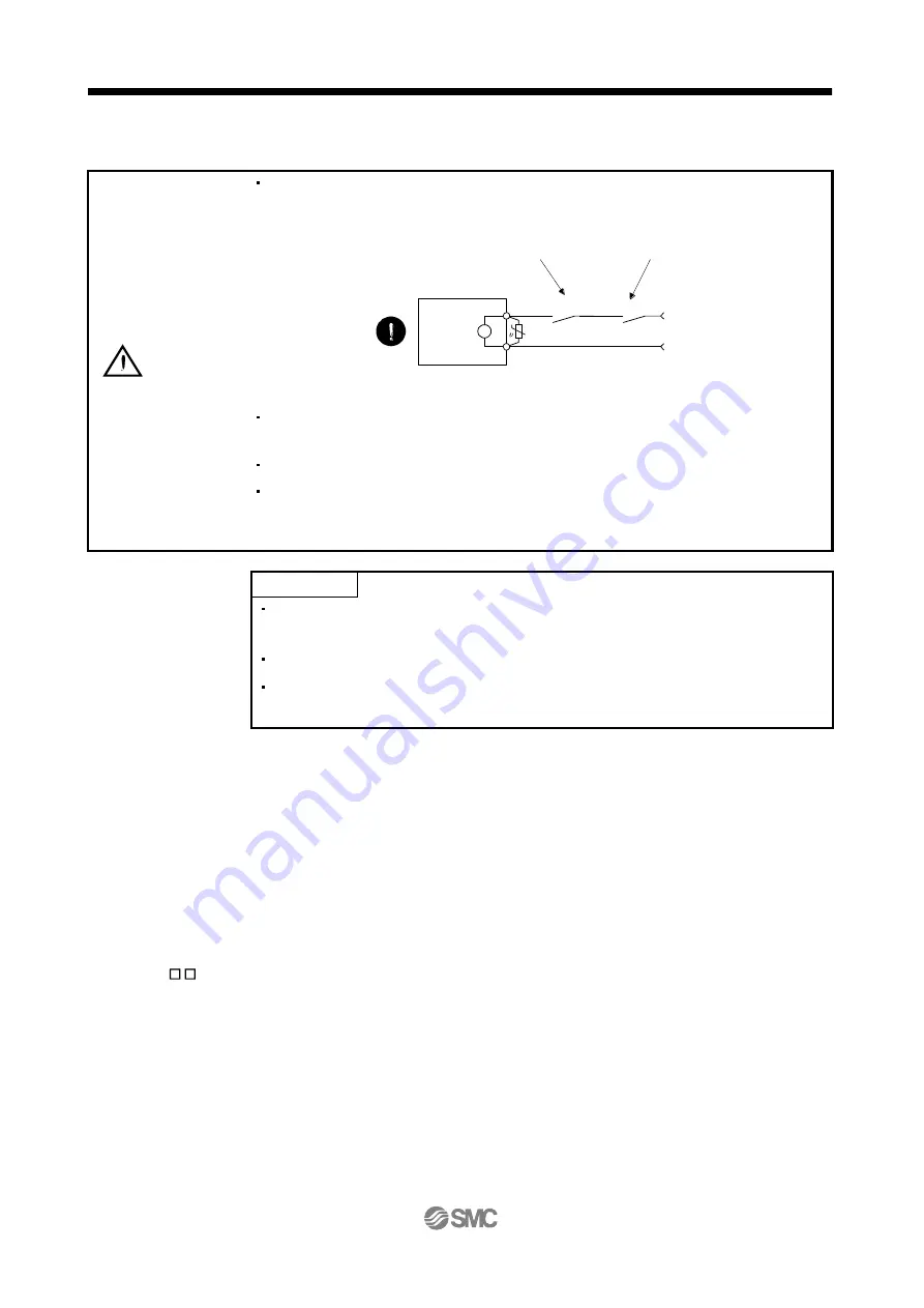
Configure a lock operation circuit which interlocks with an external emergency stop
switch.
Servo motor
Electromagnetic brake
B
RA
Contacts must be opened
with the EMG stop switch.
Contacts must be opened when ALM
(Malfunction) or MBR (Electromagnetic
brake interlock) turns off.
24 V DC
The lock is provided for holding purpose and must not be used for ordinary
braking.
Before performing the operation, be sure to confirm that the lock operates properly.
Do not use the 24VDC interface and control circuit power supplies for the lock.
Always use the power supply designed exclusively for the lock. Otherwise, a fault
may occur.
POINT
Refer to chapter 12 for specifications such as the power supply capacity and
operation delay time of the lock.
Switch off the servo-on (SON) after the servo motor has stopped.
Refer to (3) in section 12.1.3 for the selection of the surge absorbers for the
lock.
Note the following when the servo motor with a lock is used.
1) Always assign the electromagnetic brake interlock (MBR) to CN1-pin 12 by parameter No. PD18.
(MBR is assigned to CN1-pin 12 by default.)
2) The lock operates when the power (24VDC) turns off.
3) While the reset (RES) is on, the base circuit is shut off. When using the servo motor with a vertical
shaft, use the electromagnetic brake interlock (MBR).
3.11.2 Setting
(1) Set " 05 " to parameter No. PD18 to assign the electromagnetic brake interlock (MBR) to CN1-pin 12.
(2) Using parameter No. PC09 (electromagnetic brake sequence output), set a time delay (Tb) at servo-off
from lock operation to base circuit shut-off as in the timing chart shown in section 3.11.3 (1).
Lock


